This topic explains concepts used in the Policy tab.
Information on:
- Policy
- Role
- Policy Domains
- Service
- Rule
- Packet Tagging
- VLAN to Role Mapping
- Dynamic Egress
- Policy VLAN Islands
- Traffic Mirroring
- Port Groups
- Network Resource Groups
- Verifying
- Enforcing
- Controlling Client Interactions with Locks
Policy
In the Policy tab, network access policies are called Roles. See Role, below, for a description.
Role
What is a Role
A role is a set of network access services that can be applied at various access points in a policy-enabled network. A port takes on a user's role when the user authenticates. Roles are usually named for a type of user such as Student or Engineering. Often, role names match the naming conventions that already exist in the organization. A role can contain any number of services in the Policy tab.
A role can also contain default access control (VLAN) and/or class of service (priority) characteristics that will be applied to traffic not identified specifically by the set of access services contained in the role. The set of services included in a role, along with any access control or class of service defaults, determine how all network traffic will be handled at any network access point configured to use that role.
Default Role
After you have created a role, assign it as the default role for a port (see Assigning Default Roles to Ports).
Policy Domains
The Policy tab provides the ability to create multiple policy configurations by allowing you to group your roles and devices into Policy Domains. A Policy Domain contains any number of roles and a set of devices that are uniquely assigned to that particular domain. Policy Domains are centrally managed in the database and shared between the Policy tab clients.
In the Policy tab, you work in one current domain at a time. Each domain is identified by a unique name. The Domain menu lets you easily switch from one domain to another. There is no limit to the number of domains you can create, however, a device can exist in only one Policy Domain.
The first time you launch the Policy tab, you are in the Default Policy Domain. You can manage your entire network in the Default Policy Domain, or you can create multiple domains each with a different policy configuration, and assign your network devices to the appropriate domain. The roles, services, rules, VLAN membership, and class of service in this initial configuration define a suggested implementation of how network traffic can be handled. This is a starting point for a new policy deployment and often needs customization to fully leverage the power of a policy-enabled network.
The Policy tab ships with a set of domain configurations that provide ready-made workflows for common policy scenarios. Each domain configuration contains all the elements (roles, services, rules, VLAN membership, class of service) that define how network traffic is handled for each scenario. These domains are listed in the Open/Manage Domain menu.
You can import the data elements from one domain into another domain. You can also import a domain saved as a policy Database file (.pmd file) or data from a Database file into a domain, and you can export a domain or data from a domain to a .pmd file, (one file per domain) for backup and troubleshooting purposes. Verify and Enforce operations are performed only on the current domain.
In order for your network devices to be displayed on the left-panel Devices tab, they must be assigned to a Policy Domain. Initially, you must add your devices to the ExtremeCloud IQ Site Engine database. After devices have been added to the ExtremeCloud IQ Site Engine database, you can assign the devices to a Policy Domain using the Policy tab. As soon as a device is assigned to a domain, it is automatically displayed on the left-panel Devices tab. Only devices that support policy are displayed in the Policy tab.
The Policy tab automatically locks the current Policy Domain when you begin to edit the domain configuration. Other users are notified that the domain is locked and they are not be able to save their own domain changes until the lock is released. For more information, see Controlling Client Interactions with Locks. After a Policy Domain has been changed, you must save the domain to notify all clients viewing that domain of the change and automatically update their view with the new configuration.
Service
Services are sets of rules that define how network traffic for a particular network service or application should be handled by a network access device. A service might consist of only one rule governing, for example, email priority, or it might consist of a complex set of rules combining class of service, filtering, rate limiting, and access control (VLAN) assignment. The Policy tab allows you to create Local Services (services that are unique to the current domain) and Global Services (services that are common to all domains). Global Services let you easily create and manage services shared between all your domains. A service can be included in any number of roles.
As an example, you might create a service called High Priority Internet Web
Access that contains priority classification rules for traffic directed toward each of
your organization's Internet proxy servers. This service would likely contain one traffic
classification rule for each of your Internet proxy servers.
Services can be one of two types: Manual Service or Automated Service.
- Manual Service
 - This service consists of one or more traffic
classification rules you create based on your requirements.
Manual services are good for applying customized sets of rules to roles.
- This service consists of one or more traffic
classification rules you create based on your requirements.
Manual services are good for applying customized sets of rules to roles. - Automated Service
 - This service automatically creates a rule with a specified action (class
of service and/or access control), for each device in a particular network resource
group. You create a network resource group using a list of IP addresses or an IP subnet,
and then associate the group with the Automated service (see How to Create a Network Resource
Group for more information). Automated rule types include Layer 3 IP
Address and IP Socket rules, and Layer 4 IP UDP Port and IP TCP Port
rules.
- This service automatically creates a rule with a specified action (class
of service and/or access control), for each device in a particular network resource
group. You create a network resource group using a list of IP addresses or an IP subnet,
and then associate the group with the Automated service (see How to Create a Network Resource
Group for more information). Automated rule types include Layer 3 IP
Address and IP Socket rules, and Layer 4 IP UDP Port and IP TCP Port
rules.
Services provide a common language that network engineers, information technology administrators, and business managers understand. See How to Create a Service for more information.
Rule
What is a Rule
Policy rules define one element of how traffic for a particular network service or application is handled by a network access device. For example, you might create a rule that assigns a certain priority to all email traffic, by adding an 802.1p, ToS, or DiffServ value to all SMTP traffic. A policy rule can be included in any number of services and you can select the types of devices to which the rule applies. You create rules by right-clicking a Service in the Service Repository tab and selecting Create Rule
.See Traffic Classification Rules for a detailed explanation of rules.
Disabling Rules
You can elect to disable a rule during or after its creation. If you disable a rule, it is temporarily unavailable for use by the current service, but it can still be copied to other services and enabled, or re-enabled at another time for the current service. Disabling a rule is a way to temporarily remove a rule from your service without having to delete and recreate it. You disable rules by right-clicking a Service in the Service Repository tab and selecting Disable Rule.
Conflict Checking
As you create your Policy view services and rules, you can define conflicting rules. A conflict exists when two rules in the same service or role define different actions for the same traffic description. For example, two rules might have the same traffic description, but forward traffic to different VLANs, or have different priorities. ExtremeCloud IQ Site Engine ensures that conflicting rules do not coexist in the same role or service by checking rule traffic descriptions and action values, providing a message if conflicts are found, and writing the conflict information to the Event Log. If a rule is disabled, conflicts between that rule and others are ignored.
The one exception to this conflict checking behavior, is when the conflicting rules coexist in the same role, but one rule exists in a Local service and the other exists in a Global service. In this case, the rule defined in the Local service takes precedence over the rule defined in the Global service because the Local service is specific to the current domain. Consider the following example:
In the North Campus domain you have a Local service "A" that assigns an Ethertype IP rule to the Red VLAN. The "A" service is assigned to the Student Role. In addition, a Global service "B" exists that assigns Ethertype IP rules to the Blue VLAN. The "B" service is also assigned to the Student Role. In this case, the Local service takes precedence over the Global service in the North Campus domain. Note that the precedence pertains to the rule's actions: class of service (priority) and access control (VLAN). For example, if a rule in a Local service and a rule in a Global service both have the same traffic description, and the Local rule's actions apply CoS Priority 1 and no access control (no VLAN), while the Global rule's actions apply CoS Priority 2 and VLAN Blue(2), then the rule will be enforced using CoS Priority 1 and VLAN Blue(2). In addition, if either the Local or Global service has the Accounting or Security actions enabled, then they will be enforced to the devices.
Packet Tagging
Packet tagging in a Policy view environment occurs as follows:
Tagged packets and ingress filtering are processed first. Then,
VLAN ID and priority are determined.
- VLAN ID: If the packet matches an active VLAN
classification rule on the ingress port, the VID (VLAN ID) specified in the
matching VLAN classification rule is assigned. Otherwise, if there is an active
role
on the ingress port and it specifies a default VLAN, the default VID from
the active role on the ingress port is assigned. If there is no active role
and no classification rule matches, the
802.1Q PVID for the ingress port is assigned.
- Priority: If the packet matches an active priority classification rule on the ingress port, the priority specified in the matching priority classification rule is assigned. Otherwise, if there is an active role on the ingress port and it specifies a default priority, the default priority from the active role on the ingress port is assigned. If there is no active role and no classification rule matches, the 802.1Q_PPRI for the ingress port is assigned.
The set of classification rules active on a port includes statically created rules that specify the ingress port on their port list, as well as any rules established as a result of a role being applied on that port. If the port has no active role and thus no default access control (VLAN) or class of service (priority), untagged packets that do not match any classification rules are assigned a VLAN and priority from the 802.1Q and 802.1p defaults for the ingress port.
For a graphical illustration of the packet tagging process in a Policy view scenario, see the Packet Flow Diagram. The packet passes through the decision-making process illustrated in the graphic twice — one time for VLAN tagging and one time for priority tagging.
VLAN to Role Mapping
VLAN to Role mapping lets you assign a role to an end user based on a VLAN ID. There are two kinds of VLAN to Role Mapping: Authentication-Based and Tagged Packet.
- Authentication-Based VLAN to Role Mapping (RFC 3580) — Provides a way
to assign a role to a user during the authentication process, based on a VLAN
Attribute. An end user connects to a policy-enabled device that supports 802.1X
authentication using a RADIUS Server. During the authentication process, the
RADIUS server returns a VLAN ID in its RADIUS VLAN Tunnel Attribute. The device
uses the Authentication-Based VLAN to Role mapping list to determine what role
to assign to the end user, based on the VLAN Tunnel Attribute.
Authentication-Based VLAN to Role mappings are only configured at the device
level (for all devices).
NOTE: When configuring Authentication-Based VLAN to role mapping, you must enable RFC3580 VLAN Authorization on the device via the device Authentication tab. In addition, VLAN IDs must be configured on the RADIUS server for each user authorized to access the network. If a user does not have a configured VLAN ID, the default role (if there is one) or the 802.1Q PVID for the ingress port is assigned. For more information on configuring VLAN ID attributes on the RADIUS server, refer to your device firmware documentation, RFC 3580, and your RADIUS server documentation. - Tagged Packet VLAN to Role Mapping - Provides a way to let policy-enabled
devices assign a role to network traffic, based on a VLAN ID. When a device
receives network traffic that has been tagged with a VLAN ID (tagged
packet) it uses the Tagged
Packet VLAN to Role mapping list to determine what role to assign the traffic
based on the VLAN ID. Tagged Packet VLAN to Role mapping can be configured at
the device level (all devices) and at the port level (for an individual port on
a device). A VLAN can only be mapped to one role at the device level, but the
same VLAN can be mapped to a different role at the port level. A mapping does
not have to exist at the device level to be created at the port level, and
port-level mappings will override any device-level mappings.
NOTE: TCI Overwrite Requirement
-- Tagged Packet VLAN to Role Mapping will apply the Role definition to incoming packets using a mapped VLAN. This definition will apply a COS and determine if the packet is discarded or permitted, and if TCI Overwrite is enabled will re-specify the VLAN ID defined by the Rule / Role Default. If TCI Overwrite is disabled, the packet will egress (if permitted by the Rule Hit) with the original VLAN ID it ingressed with.
-- If supported by the device, you can enable TCI Overwrite for an individual role in the role's General tab. The stackable devices support rewriting the CoS values but not the VLAN ID.
To configure VLAN to Role Mapping in the Policy view, use the role's Mappings tab and/or the VLAN's General tab.
Dynamic Egress
In the VLANs tab, you can enable Dynamic Egress for a VLAN by selecting the Dynamic Egress checkbox when you select a VLAN.
When Dynamic Egress is enabled for a VLAN, any time a device tags a packet with that
VLAN ID, the ingress port is automatically added to the VLAN's egress list,
enabling the reply packet to be forwarded back to the source. This means you do
not need to add the ingress port to the VLAN's egress list manually. (See Example 1,
below.)
Dynamic Egress affects only the egress lists for the source and destination ingress ports.
However, GVRP (GARP VLAN Registration Protocol) automatically adds the
interswitch ingress ports to the egress lists of VLANs. (See Example 2, below.)
You can enable GVRP for the domain by selecting the Global Domain Settings > GVRP > Enable menu option.
| NOTE: | If you do not want GVRP enabled on your network, you can disable it by
selecting the Global Domain Settings > GVRP > Disable menu option.
If necessary, you can then manually configure the interswitch ports to do what
GVRP does automatically, using local management to
set up your interswitch links as Q trunks. The trunk ports will be
automatically added to the egress lists of all the VLANs at the time of trunk
configuration. For more information on using GVRP in the Policy view, see the section on
Setting Domain GVRP Status below.
|
|---|
When you disable Dynamic Egress for a VLAN, the VLAN effectively becomes a discard VLAN. Since the destination port is not added to the egress list of the VLAN, the device discards the traffic. If you want a VLAN to act as a discard VLAN, disable Dynamic Egress for that VLAN. (See Example 3, below.)
If an endstation is talking to a "silent" endstation which does not send responses, like a printer, you need to add the silent endstation's ingress port to the VLAN's egress list manually using local management. Dynamic Egress and GVRP take care of adding the other ingress ports to the VLAN's egress list. (See Example 4, below.)
| CAUTION: | If no packets are tagged with the applicable VLAN on a port within five minutes,
Dynamic Egress list entries time out. The result is that ExtremeCloud IQ Site Engine indicates that the endstation is "silent" if the VLAN has not been used within that time period. For example, if there
is a "telnet" rule and two users (A and B) are on ports whose role includes a service
containing the "telnet" rule, if User B has not utilized the "telnet" rule within the
five minute time frame, User A is not able to telnet to User B. For this reason,
the best application of Dynamic Egress is for containing undirected traffic on "chatty"
clients which utilize, for example, IPX, NetBIOS, AppleTalk, and/or broadcast/multicast
protocols such as routing protocols. |
|---|
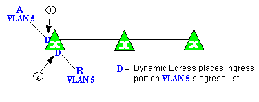
Example 1: Dynamic Egress Enabled
In this example, Dynamic Egress is enabled for VLAN 5. When source endstation A is tagged with VLAN 5, Dynamic Egress places A's ingress port (1) on VLAN 5's egress list. When destination endstation B's traffic is tagged with VLAN 5, Dynamic Egress places B's ingress port (2) on VLAN 5's egress list. The device can then forward traffic to both endstations.
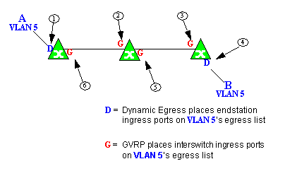
Example 2: Dynamic Egress + GVRP
In this example, Dynamic Egress is enabled for VLAN 5, and the destination endstation, B, is on a different device from the source endstation, A. When A is tagged with VLAN 5, Dynamic Egress places A's ingress port (1) on VLAN 5's egress list. GVRP then places interswitch ingress ports (2) and (3) on VLAN 5's egress list. When B's traffic is tagged with VLAN 5, Dynamic Egress places B's ingress port (4) on VLAN 5's egress list. GVRP then places interswitch ingress ports (5) and (6) on VLAN 5's egress list. The devices can then forward traffic to both endstations.
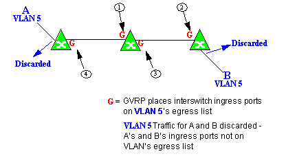
Example 3: Dynamic Egress Disabled
In this example, Dynamic Egress is disabled. When source endstation A is tagged with VLAN 5, A's ingress port is not placed on VLAN 5's egress list. GVRP places interswitch ingress ports (1) and (2) on VLAN 5's egress list. When B's traffic is tagged with VLAN 5, B's ingress port is not placed on VLAN5's egress list. GVRP places interswitch ingress ports (3) and (4) on VLAN 5's egress list. But VLAN 5 traffic for both A and B is discarded, because VLAN 5 is not aware of the ingress ports for A and B.
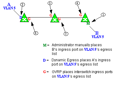
In this example, Dynamic Egress is enabled for VLAN 5, but the destination endstation, B, is a "silent" endpoint, like a printer. Endstation B does not send responses, so the Administrator must place B's ingress port on VLAN 5's egress list manually (1). When A is tagged with VLAN 5, Dynamic Egress places A's ingress port (2) on VLAN 5's egress list. GVRP then places interswitch ingress ports (3) and (4), then (5) and (6) on VLAN 5's egress list. Endstation A is then able to communicate with the printer.
Setting Domain GVRP Status
The Policy view allows you to set the domain GVRP (GARP VLAN Registration Protocol) status via the Edit menu. There are three GVRP status options. To set the GVRP status for all the devices in the current domain, select a status and then enforce.
- Ignore — When this option is selected, ExtremeCloud IQ Site Engine ignores the GVRP configuration on a device during an Enforce operation. This allows you to configure some network switches with GVRP enabled and others with GVRP disabled, according to their configuration requirements.
- Enable — When this option is selected, GVRP is enabled for the devices in the current domain.
- Disable — Select this option if you do not want GVRP enabled on the devices in the current domain. Disabling GVRP can affect connectivity through ports with VLANs that rely on Dynamic Egress. If GVRP is disabled, rules using VLAN containment do not work properly unless the VLANs have been pre-configured on the devices outside of ExtremeCloud IQ Site Engine.
The following table shows how domain GVRP status affects device-level and port-level GVRP status when an Enforce operation is performed.
| Domain GVRP Status | Device Set on Enforce |
|---|---|
| Domain GVRP status is set to Ignore. | No GVRP status is written to devices on Enforce. |
| Domain GVRP status is set to Enable and the device-level GVRP is enabled. | No GVRP status is written to the device on Enforce. |
| Domain GVRP status is set to Enable and the device-level GVRP is disabled. | Device-level GVRP status and port-level GVRP status is set to enabled on Enforce. |
| Domain GVRP status is set to Disable and the device-level GVRP is disabled. | No GVRP status is written to the device on Enforce. |
| Domain GVRP status is set to Disable and the device-level GVRP is enabled. | Device level GVRP status is set to disabled and no change is made to the port-level GVRP status on Enforce. |
Policy VLAN Islands
The Policy view offers you the ability to set up Policy VLAN Islands which enable you to deploy a policy across your network, while restricting user access to only selected local devices. For example, if you want to have a guest VLAN but you do not want the guests in one facility to be able to communicate with guests in another facility, you can set up a VLAN island containing only selected devices in each facility, with access controlled by island VLANs.
- Global VLAN — Global VLANs are written to all selected devices with the same VID. They are referenced in the format <VID[name]>.
- Island VLAN — An Island VLAN is a conceptual VLAN and does not have an actual VID. The VID is assigned automatically based on the island it belongs to.
| NOTE: | The Policy view provides management of Global VLAN settings, but does not provide management of Island VLANs beyond setting the appropriate VIDs in the Role defaults and Rule access control actions. Also, you must manage separately other related settings in the qBridgeMib such as name, and dynamic egress values. |
|---|
See How to Create a Policy VLAN Island for more information.
Traffic Mirroring
The Policy view provides policy-based traffic mirroring functionality that allows network administrators to monitor traffic received at a particular port on the network, by defining a class of traffic that will be duplicated (mirrored) to another port on that same device where the traffic can then be analyzed. Traffic mirroring can be configured for a rule (based on a traffic classification) or as a role default action. Only incoming traffic can be mirrored using policy-based traffic mirroring, and the traffic mirroring configuration takes precedence over regular port-based mirroring.
Traffic mirroring uses existing the Policy view port groups (created using the Port Groups tab) to specify the ports where the mirrored traffic will be sent for monitoring and analysis. When an end user connects to the device where the specified ports exist, and is assigned the role that has traffic mirroring configured, then there is a traffic mirror set up for the port the end user connected to. However, if the end user is assigned a role that does not have traffic mirroring configured, or if the end user connects to a device that doesn't have any ports in the specified port groups, then no traffic mirror will exist.
Examples of how traffic mirroring might be used include:
- Mirroring the traffic from suspicious users based on their MAC or IP address.
- Monitoring VoIP calls by IP address or port range.
- Mirroring traffic to optimized IDS systems, for example one system for all HTTP traffic (to look for suspicious websites) or one system for all emails (to look for spam).
- Mirroring traffic to ExtremeAnalytics appliances for use in ExtremeCloud IQ Site Engine application identification reports and analysis.
For information on configuring traffic mirroring, see the Role tab and the Rule General tab.
Port Groups
ExtremeCloud IQ Site Engine allows ports to be combined into groups, similar to the way services can be combined into service groups. Port groups enable you to configure multiple ports on the same device or on different devices simultaneously, or to retrieve port information from them. You can view port groups on the left-panel Port Groups tab.
The Policy view provides you with several commonly used port groups for your convenience, called Pre-Defined Port Groups. You can also create your own port groups, called User-Defined Port Groups.
User-Defined Port Groups
The Policy view also enables you to create your own port groups and select individual ports to add to the group.
Network Resource Groups
Network Resource Groups provide a quick and easy way to define traffic classification rules for groups of network resources such as routers, VoIP (Voice over IP) gateways, and servers. The default Policy domain configuration contains examples of network resource groups that you might want to create, such as Internet Proxy Servers and SAP Servers. Use the Network Resource Configuration window to view and define your network resource groups. See How to Create a Network Resource for more information.
After a network resource group has been defined, you can associate it with an Automated service (see How to Create a Service for more information). The Automated service automatically creates a rule with a specified action (class of service and/or access control), for each resource in the network resource group. Automated rule types include Layer 2 MAC Address rules, Layer 3 IP Address and IP Socket rules, and Layer 4 IP UDP Port and IP TCP Port rules.
Network Resource Topologies
Network Resource Topologies are used to divide the devices in a domain into groups called islands. Each network resource group specifies a topology and can then define a unique resource list for each island within that topology, allowing user access to resources on the network based on the physical location at which they authenticate.
For example, you could create a topology called "Campus Printers" that could be used to restrict printer access to only the printers in the building where the end user is physically located. This topology might define islands such as "Library," "Admissions Office," or "Science Building." Each island would include the network devices for that location. Then, in the Network Resource Group that specifies this topology, there would be resource lists that define the printers for each of those islands.
In addition to defining topologies based on physical location (such as geographic region, corporate offices, or campus buildings) a topology could also be used to define resources based on the departments within a company (such as Sales, IT, or Human Resources).
When you create a topology, it contains a Default Island that includes all the devices in your domain. You can then create additional islands and distribute your devices between the different islands according to your needs. Each device in a domain must belong to one island in each topology. You can set any island as the Default island for new devices that are added to the domain.
Verifying
The Verify feature lets you verify that the roles in your current domain
have been enforced. Verify operations are performed only on the current domain.
The Verify operation compares the roles currently in effect (enforced)
on your domain devices with the roles defined in the current Policy Domain.
| NOTE: | If you perform a Verify operation following an Import Policy Configuration from Device, the Verify can fail. This is because the import operation imports only roles and rules from the device, not the complete policy configuration. Also, when you import device-specific rules, these rules are converted to a Rule Type of "All Devices," and this will cause Verify to fail. If you want the rules to be device-specific, you will have to change their Rule Type via the Rule General tab after the import and prior to Enforce. |
|---|
You can verify using the Open/Manage Domain > Verify Domain menu option, both of which verify the information on all the devices in the current domain. You can also selectively verify on individual devices or device groups in the domain by right-clicking the device or group in the left panel or in the right-panel Details View tab for the Devices folder or Device Group folder, and choosing Verify from the menu.
After verifying, you see a window that reports any discrepancies. The title bar of the window lets you know if the verify was done on all devices in the domain, or a subset of devices. From this window, you can select Enforce Domain to open the Enforce Preview window, where you can view the effects enforcing the current role set would have, prior to actually enforcing. You can also view the full results of the Verify operation in the event log, which displays any discrepancies and statistics of the operation itself.
Enforcing
In the Policy tab, enforcing means writing role information to a device or devices. Enforce operations are performed only on the current domain. Any time you add, make a change to, or delete a role or any part of it (any of its services and/or rules), the devices in your current domain need to be informed of the change, otherwise the role will not take effect. To determine if the roles currently in effect on your domain devices match the set of roles you have defined in your current Policy Domain configuration, use the Verify feature.
When an Enforce is initiated, the Policy Domain is locked to prevent other clients from enforcing at the same time. Different Policy Domains can be enforced at the same time, but if another user attempts to enforce the same domain at the same time, that user will be notified that the domain is already locked.
To enforce, select the Open/Manage Domains > Enforce Domain menu option. You can also selectively enforce on individual devices by right-clicking the device in the Devices tab left panel or in the right-panel Devices tab and choosing Enforce from the menu. Only users that have been assigned the Enforce capability are allowed to perform an Enforce.
Controlling Client Interactions with Locks
Because the Policy view uses a Client/Server architecture, it is important to maintain a proper sequence of client interactions to ensure a consistent view of Policy Domains among all clients. To do this, the Policy view uses Server Locks to manage user interactions. When a user begins editing a Policy Domain (for example by assigning devices or adding a role), a lock is acquired for that domain at the server. That lock is not released until the same user saves the domain data. This guarantees a consistent view of that domain for all clients. Users are given the option of revoking locks held by other users. This protects against the possibility that users forget they have locked a domain and keep that lock for an extended period of time.
A domain is locked automatically when a user begins to edit the domain data or a user can lock/unlock a domain by selecting the Lock toolbar button. When a domain is locked, the title bar states that the policy data is being edited and specifies the user who has locked the domain. Other Policy view clients are notified that the domain is locked and they will not be able to save their own domain changes until the lock is released.
Here are some important things to remember about locks:
- Locks operate on individual Policy Domains. When a user edits a domain, a lock is acquired for that domain and it remains locked until the same user saves the domain data or the lock is revoked by another user. You cannot save a domain that is locked by another user.
- During Enforce, a lock is acquired on the domain which is being enforced. This ensures a consistent view of the domain while it is being used by the server.
- When devices are being assigned to a Policy Domain, multiple domains can be locked concurrently. This will happen if devices from one domain are being reassigned to another domain. In this case, locks for both domains are acquired.
- When a lock is revoked, the last domain save "wins." While consistency is always maintained by the server, the order of domain saves cannot be guaranteed when locks are revoked, and consequently work done by one user can be lost.
You can view server locks for all clients via the Options > Server Information tab.
For information on related help topics:
![]()