The ExtremeCloud IQ Site Engine Maps feature lets you create maps of the devices and wireless access points (APs) on your network. Begin by selecting a background image to serve as a map, such as a building or floor plan, and then position your managed devices and wireless APs on the map. For example, a typical map might present an office floor plan that shows the location of wireless access points.
For introductory information on maps in ExtremeCloud IQ Site Engine, see ExtremeCloud IQ Site Engine Maps.
This Help topic provides the following information on creating and editing maps.
- Creating a New Map
- Importing a Map
- Adding Devices/APs from ExtremeCloud IQ Site Engine Devices and Wireless
- Creating a Manual Link Between Devices
- Adding Map Links
- Setting the Map Scale
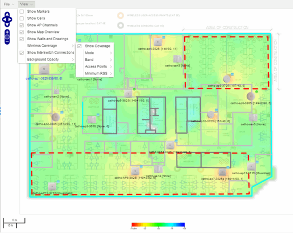
For information on creating custom floor plans, advanced location (triangulation), and wireless coverage maps, see Advanced Map Features.
In order to create or edit Maps, you must be a member of an authorization group assigned the OneView > Maps > Maps Read/Write Access capability.
Creating a Map
The instructions in this section describe how to create a new Device map.
- Launch ExtremeCloud IQ Site Engine and select the Network tab.
- Open the Devices tab.
- In the left-panel select Sites.
- Right-click a site or map and select Maps/Sites > Create Map.
- Enter a name for the map and select OK.
- Select File > Properties to open the Map Properties window from which you can edit the map criteria.
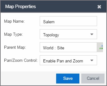
- In the Map Name field, change the name for the map, if necessary.
- In the Map Type drop-down list, select the type of map you are creating.
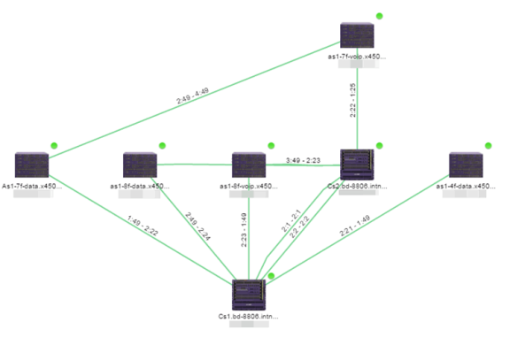
- Topology (default) - A topology map shows the state and speed of the network connections between devices as well as the state of the devices in the network.
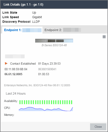
Double-clicking a connection opens the Link Details window from which you can view additional details about the network connection and the devices it links.
- Topology - Background — Use a custom image to serve as the background of your map. The Map feature supports images in PNG, GIF, and JPG (without transparency) formats. The maximum image size is 3,000 x 2,000 pixels. Images larger than this are automatically scaled down to the maximum size allowed. To use an image larger than 3,000 x 2,000 pixels, open the
NSJBoss.propertiesfile and edit the pixel value of theoneView.maxImageSize=3000x2000line.CAUTION: Increasing the oneView.maxImageSize value may cause stability issues.
If you select this option, a Map Image field displays under the Map Type field. In the Map Image field, use the drop-down list to select an image or select the button to open a window where you can select a local image and upload it to the ExtremeCloud IQ Site Engine server.
CAUTION: If you upload a map image and an image with the same name already exists, the existing image is replaced. - Floorplan — Use the Floorplan map to display coverage of wireless APs within a building floorplan.
 If you select Floorplan, select the map Environment, which is the type of environment where your network devices are physically located. If your map includes wireless APs, the environment is used for RSS-based (Received Signal Strength) location services to help determine the radius of the circle displayed around an AP following a wireless client search. The radius shows the possible area where the client is located. For example, if you select open space environment, then the radius of the circle is larger than if you select brick walls environment because the AP's radio frequencies are not be obstructed by any walls, and the area where a client might be located is larger. See Finding a Wireless Client for more information.
 - Open space — The wireless APs are located in an environment with no walls or cubicles.
- Office cubicles — The wireless APs are located in an environment with cubicle offices present.
- Drywall — The wireless APs are located in an environment where the office wall composition is drywall.
- Brick walls — The wireless APs are located in an environment where there are brick walls present.
- Custom — Use this option to create custom floor plans. For more information, see Advanced Map Features.
- Geographic — Displays a global or regional map where network locations are shown geographically.
For information on creating a custom floor plan design, see Designing a Floor Plan.
A Map Image field is displayed under the Environment field. In the Map Image field, use the drop-down list to select an image or select Add (
) to open a window where you can select a local image and upload it to the ExtremeCloud IQ Site Engine server.NOTE: If you upload a map image and an image with the same name already exists, the existing image is replaced.
The Map feature supports images in PNG, GIF, and JPG (without transparency) formats.. The maximum image size is 3,000 x 2,000 pixels. Images larger than this are automatically scaled down to the maximum size allowed. To use an image larger than 3,000 x 2,000 pixels, open theNSJBoss.propertiesfile and edit the pixel value of theoneView.maxImageSize=3000x2000line.CAUTION: Increasing the oneView.maxImageSize value may cause stability issues and performance issues when generating a heatmap. NOTE: The geographic map type is hosted by OpenStreetMap on an external server. For users with security concerns or if access to third-party servers is prohibited, use the topology map type. 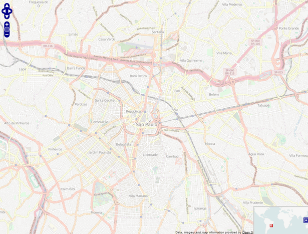
- Topology (default) - A topology map shows the state and speed of the network connections between devices as well as the state of the devices in the network.
- Use the
 button to select the Parent Map, the map the new map is nested under in the Maps navigation tree. Changing the map's parent saves the current map properties and updates the map tree.
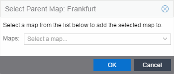
- Select Save.
- Select the Pan/Zoom Control option. This option determines whether or not the Pan and/or Zoom controls are available when viewing the map. (Pan and Zoom are always available while editing a map.) This allows you to disable the controls for fixed maps, like world or city maps. For example, if a person viewing a map changes the location and zoom using these controls, those changes are saved and presented to the next person who views the map. This might create confusion over what the map is designed to display.
 The Pan control allows you to move left/right and up/down in the map.
  The Zoom control lets you zoom in and out of the map.
- Add your devices, APs, Links, or port extenders to the map you are currently editing by selecting File > Add > Devices/APs/Map Link/Port Extenders. This opens the Add window.
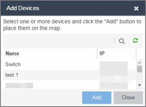 Use the Search icon to locate a specific device, AP, or port extender in the Add Device, Add AP, or Add Port Extenders windows, respectively, or select another Map to which to link from the drop-down list in the Add Link To Map window. Select the Add button to add the device, AP, link, or port extender to your network map.
 - After your devices and/or APs and port extenders are located on your map, manually manipulate the devices, APs, links, and port extenders on the map, or organize them automatically by selecting View > Automatic Layout. The Device Layout window opens. Select one of the following layouts to automatically organize the devices, APs and links on your map:
- Natural — Organizes devices, APs, and links such that the fewest number of network connections overlap.
- Hierarchical — Organizes devices, APs, and links in a tree pattern.
- Circular — Organizes devices, APs, and links in a circular pattern.
- Select File > Save button to save the map.
- The map is now available for viewing by selecting it in the navigation tree. To edit a map, right-click on the map and select Maps > Edit Map or select the Edit button in the Map Properties panel.
| NOTE: | You cannot create a new map if you are currently editing another map. |
The new map is initially blank unless you create it from a device or AP by selecting the device or AP, selecting the Menu icon (
 ) or right-clicking the device or AP and selecting Maps > Create Map. To begin adding devices, APs and links to the map, proceed to Step 7. Proceed to the following step to edit the map properties.
| NOTE: | Map devices and APs do not show their current status until you save the map. |
Importing a Map
You can also import a saved map by performing the following steps.
- Launch ExtremeCloud IQ Site Engine and select the Network tab.
- Open the Devices tab.
- Right-click a map in the left-panel Groups/Maps Navigation Tree and select Maps > Import Map.
The Import Map window opens. - Navigate to the Map file on your local drive or network drive.
- Configure your import options.
- Select Import.
Adding Devices/APs from ExtremeCloud IQ Site Engine Devices and Wireless
You can quickly add devices and APs to your maps directly from the Devices list or from the navigation tree on the ExtremeCloud IQ Site Engine Network and Wireless tabs. You can add them to a specific map, or create new maps based on device or AP system location.
Add to a Specific Map
Use these steps to add devices or APs to a map you created. For example, use these steps to search for all your S-Series devices on the Network tab and add them to a map.
- On the Network > Devices tab, select All Devices in the drop-down list in the left-panel.
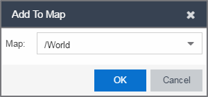
- Right-click on one or more devices and select Maps > Add to Map (as shown below). On the Wireless tab, select the Access Points report, right-click on one or more APs, and select Add to Map.
- In the Add to Map window, use the drop-down list to select the desired map. Select OK to add the devices or APs to the map.
- Open the Maps page and select the map to which you added the devices. Right-click on the map and select Edit Map. You can now position the devices as desired.
- Select the Save button to save the device to the map.
Add to New Maps Based on Location
Use these steps to add devices or APs to new maps based on well-named system locations that reflect the desired map structure. For example, if your devices are assigned system locations according to the following structure: US/Boston/Third Floor/Closet One/Rack One/Shelf One, typically, a map would be created to the Third Floor level, and then you manually position the devices in the correct location on the map.
| NOTE: | The map is not created if the endpoint location matches a site that currently exists in ExtremeCloud IQ Site Engine. |
- On the Network > Devices tab, right-click on one or more devices and select Maps > Create Maps for Locations.
On the Wireless tab, select the Access Points report, right-click on one or more APs, and select Maps > Create Maps for Locations. - The Create Maps Based on Location window opens. The window contains a preview panel displaying the number of maps and the map titles that result, based on the system locations of your selected devices or APs.
For example, as shown in the following screen shot, you are adding 17 APs to a map. This creates four new maps based on the access points' system location structure: NORA, Salem, Salem building, and Salem Warehouse and Shipping.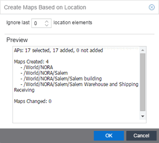
If you want all the devices on one map, set the Location Option to ignore the last 1 location elements, which is the Salem building location. If you do that, then only two maps are created: NORA and Salem.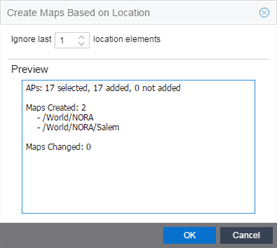
- Select OK to create the maps and add the APs.
- Open the World Site navigation tree in the left-panel and locate the new maps. Right-click on the map and select Maps > Edit Map. You can now position the APs as desired.
- Select the Save button to save the devices/APs to the map.
Creating a Manual Link Between Devices
You can manually create links between devices on a map.
- Right-click one of the devices to which you are adding the link.
- Select Create Link.
The Create a Manual Link window displays. - Expand the device in the Name column of the From Port section of the window and select the port to which the link connects.
- Select the other device to which the link connects in the Select Device drop-down list.
- Expand the device in the Name column of the To Port section of the window and select the port to which the link connects.
- Select OK to add the link to the map.
NOTES: The Link State for a manual link is derived from the Status of the ports to which it connects.
Delete a manual link via the Link Details window by double-clicking the link in the map.
Adding Map Links
You can use map links to jump from one map to another. Map links display the name of the map and an aggregated alarm/device status for the linked map. Double-click on the link to go to the linked map.
For example, the following map link lets you jump to the Second Floor map. The link is green, indicating there are no devices with alarms on the Second Floor map.
The following map link lets you jump to the First Floor map. The link is red, indicating there is an alarm for a device on the First Floor map.
Use the following steps to add a link to a map.
- In the Maps navigation tree, right-click on the map from which you want to link and select Maps > Edit Map or select File > Edit button in the map properties panel.
- The map's property panel opens in Edit mode. Select File > Add > Map Link.
- The Add Link to Map window opens.
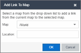
- From the Map drop-down list, select the map to which you want to link.
- Enter information in Location about the location to which the link connects and select OK.
- The map link is added to the map and can be repositioned, if desired.
- Select the Save button to save the map and close the properties panel.
Setting the Map Scale
The map scale appears in the lower left corner of a map and can be changed to accurately reflect your map image.
Use the following steps to set the scale for a map.
- In the Maps page's navigation tree, right-click on the map and select Maps > Edit Map or select the File > Edit button in the map properties panel.
- Select the map scale in the map's footer panel to open the Set Map Scale window.

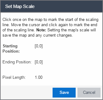
- To set the scale, you must measure something in the map using a scaling line, and then set the measurement for the line. For example, in an office floor plan measure a scaling line on the opening of an office. If you know the office doors are 33 inches wide, enter that as the scaling line measurement.
- Select on the map to mark the start of the scaling line. Move the cursor and select again to mark the end of the scaling line.
- Enter the line length and units.
- Select Save. The map scale is automatically adjusted and the map is saved.
For information on related help topics: