This window allows you to preview changes you make to a device configuration and then enforce them to the device.
To access this window, select Enforce Preview in the Configure Device window.
The Compare Device Configuration window is divided into three sections:
Device Details
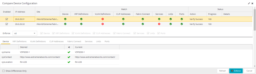
The top of the window displays a list of the devices you selected to verify. Select a device in the table at the top of the window to display the configuration for that device in the Device Configuration Detail table at the bottom of the window.
The data in this section is divided into Match and Status columns:
Match Column
Devices on which the current configuration matches the desired configuration display a check icon ( ), while devices on which differences are detected display a red x (
 ).
).
Status Column
The Status column displays the details of the status of the configuration matches in the Match column.
Enforce Options
The Enforce Options section of the window enables you to push the changes you made to the device, view and compare the changes to the current 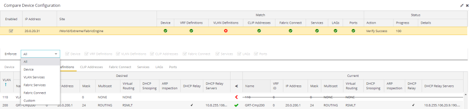
Select an option from the Enforce drop-down list to push the changes you make to the device or the specific service you select. Your selection from the drop-down list displays the changes to the configurations that are being pushed to the device in the Device Configuration Detail Table at the bottom of the window.
| NOTES: |
Device is the default option for the Enforce Options window. Use Enforce to verify whether the settings you want to configure on the device require other settings to also be set on the device. The Enforce fails if the other required settings are not configured for the changes you want to make. |
The following options are included in the Enforce drop-down list:
- All
- To push configuration changes to multiple components of the device, select All. The Device, VRF Definitions, VLAN Definitions, CLIP Address, Topology, Services, LAGs, and Ports tabs in the Device Configuration Detail table become available for you to view the changes and compare them to the current configuration.
- Device
- To view configuration changes to the device, select Device. The Device tab in the Device Configuration Detail table becomes available for you to view the changes and compare them to the current configuration.
- VLAN Services
- To push configuration changes to the VLAN, select VLAN Services. The VRF Definitions, VLAN Definitions, LAGs, and Ports tabs in the Device Configuration Detail table become available for you to view the changes and compare them to the current configuration.
In addition, the VLAN Details grid opens at the bottom of the Device Configuration table. The grid provides additional details about the changes you made to the VLAN: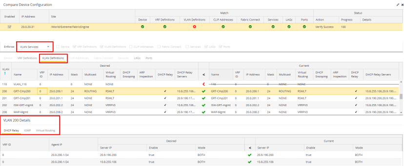
- DHCP Relay
- Displays details of changes you've made to the DHCP relay servers enabled for the VLAN.
The VLAN Details grid includes the following tabs:
- Fabric Services
- To push configuration changes to Fabric Services on the device, select Fabric Services. The VRF Definitions, VLAN Definitions, CLIP Addresses, Services, LAGs, and Ports tabs in the Device Configuration Detail table become available for you to view the changes and compare them to the current configuration.
- Fabric Topology
- To view the configuration changes to the fabric topology, select Fabric Topology. The Fabric Connect tab in the Device Configuration Detail table becomes available for you to view the changes and compare them to the current configuration.
- Custom
- The Custom option enables you to select which tabs to display in the Device Configuration Detail table. Use the check boxes to the right of the Enforce button to select the tabs you want to include in the table.
| NOTE: | Device is the default option for the Enforce Options window. |
| IMPORTANT: |
When performing an enforce on the following options, ExtremeCloud IQ Site Engine validates your changes:
An error displays if you are attempting to enforce changes that are not valid for the device. |
|---|
Device Configuration Detail Table
The Device Configuration Detail table includes several tabs:
The configurations are separated into two columns on each tab:
- The Desired column shows the configuration you are saving to the device on the next enforce.
- The Current column shows the configuration currently on the device.
A check mark between the columns ( ) indicates the Current configuration matches the Desired configuration.
A left arrow icon ( ) indicates the configurations do not match. Selecting it copies the Current configuration to the Desired configuration so no configuration change is made when enforcing the device.
Device
The Device tab displays any changes to basic information about the device.
VRF Definitions
The VRF Definitions tab displays any changes to the configuration of VRFs on the device.
- Direct Route
- Select to indicate the service sends IP packets directly to another device without going through a third device.
- Default Gateway
- Enter the IP address of the switch's default gateway. If a device is ZTP+-enabled, the site's ZTP+ Device default gateway displays.
VLAN Definitions
The VLAN Definitions tab displays the changes to the configuration of VLANs on the device.
- VLAN
- A unique numerical identifier of the VLAN.
- IGMP Version
- Indicates which version of IGMP is utilized on the port (Version 1 or Version 2).
- IGMP Querier
- The address of the IGMP Querier. This feature is used when there is no multicast router in the VLAN to originate the queries.
- Virtual Routing
- Displays the version of VRRP the default gateway is using:
- NONE — Virtual routing is not configured on the VLAN.
- VRRPv2 — VRRP version 2 is configured on the virtual router. VRRP version 2 only supports IP addresses in IPv4 format.
- VRRPv3 — VRRP version 3 is configured on the virtual router. VRRP version 3 supports IP addresses in both IPv4 and IPv6 formats.
- DvR -DvR is configured on the VLAN. There are several requirements that must be met to configure DvR on a VLAN, including:
- The VLAN must have an IP address and prefix.
- The DvR IP address must be IPv4.
- The DvR IP address must fall within the VLAN's subnet.
- The DvR IP address cannot be reused across multiple VLANs on the device.
- The VLAN must have an L2VSN associated with it.
- If the VLAN is using on a non-zero VRF ID, the VLAN must also have:
- An L3VSN associated with the VRF.
- The VRF must have the unicast option enabled.
- Devices participating in DvR as controllers must have non-zero IPv4 ISIS Source Addresses.
- Devices participating in DvR must have IPv4 Shortcuts and Multicast enabled.
- RSMLT — Routing Redundancy Method is configured on the VLAN. RSMLT requires that a Virtual IST is configured. If the device is not configured as a vIST pair, RSMLT can be selected, but the feature is not active. Once the vIST is configured, RSMLT becomes active.
NOTES: Virtual Routing is only supported on VOSS/Fabric Engine devices.
VOSS/Fabric Enginedevices support a new "dvr-one-ip" feature in the 8.2 release that allows you to share an IP address between a VLAN and its DvR interface. ExtremeCloud IQ Site Engine currently does not support the "dvr-one-ip" feature and cannot read or enforce configurations of this type. Configure VOSS/Fabric Engine device IP addresses on VLANs and their DvR interfaces through the VLAN Definitions tab.
- Virtual Routing Address
- The IP address for the virtual router. The Virtual Routing address must be in the same subnet as the VLAN subnet address.
- VRRP ID
- An identifier devices use to determine peer devices that participate in a VRRP (Virtual Routing Redundancy Protocol) virtual routing interface.
- VRRP Priority
- A value used by VRRP peers to determine the role of each of the devices in the VLAN. The default value is 100. The device with the largest value is assigned the role of Controller. For example, in a VLAN with two routers, one with a VRRP Priority of 200 and one with a VRRP Priority of 100, the router with a VRRP Priority of 200 becomes the Controller. In the event of identical priority numbers, the devices use the MAC address to determine priority.
- VRRP Backup Master
- This option determines if the backup router is able to forward traffic independently outside of the VLAN (enabled), or must forward the traffic to the Controller router before it is forwarded outside of the VLAN (disabled).
- VRRP Advertisement Interval
- Indicates frequency (in seconds) that protocol packets are sent from the virtual router in the VLAN.
- VRRP Hold Down Timer
- Indicates the amount of time (in hundredths of a second) that the backup router waits for the primary router to respond before it becomes the primary router.
- DHCP Snooping
- Indicates whether DHCP snooping is enabled for the VLAN. DHCP Snooping is a Layer 2 security feature, that provides network security by filtering untrusted DHCP messages received from the external network causing traffic attacks within the network. DHCP Snooping is based on the concept of trusted versus untrusted switch ports. Switch ports configured as trusted can forward DHCP Replies, and the untrusted switch ports cannot. DHCP Snooping acts like a firewall between untrusted hosts and DHCP servers.
- ARP Inspection
- Indicates whether ARP inspection is enabled. Dynamic ARP Inspection (DAI) is a security feature that validates ARP packets in the network. Without DAI, a malicious user can attack hosts, switches, and routers connected to the Layer 2 network by poisoning the ARP caches of systems connected to the subnet, and intercepting traffic intended for other hosts on the subnet. DAI prevents these attacks by intercepting, logging, and discarding the ARP packets with invalid IP to MAC address bindings. The switch dynamically builds the address binding table from the information gathered from the DHCP requests and replies when DHCP Snooping is enabled. The switch pairs the MAC address from the DHCP request with the IP address from the DHCP reply to create an entry in the DHCP binding table. When you enable DAI, the switch filters ARP packets on untrusted ports based on the source MAC and IP addresses seen on the switch port. The switch forwards an ARP packet when the source MAC and IP address matches an entry in the address binding table. Otherwise, the switch drops the ARP packet.
NOTE: DHCP Snooping must be enabled to use ARP Inspection.
- DHCP Relay
- Indicates whether a Dynamic Host Configuration Protocol relay server is enabled for the VLAN. A DHCP relay receives and converts a DHCP broadcast message to dynamically assign an IP address to a device on the network.
- DHCP Relay Servers
- The IP addresses of the DHCP relay servers for the VLAN.
NOTE: Select Manage to open the Manage DHCP Relay Servers window, where you can add or delete DHCP relay servers.
CLIP Addresses
Use the CLIP Addresses tab to view changes to IPv4 and IPv6 CLIP Addresses on your device.
- Prefix Length
- Displays the number of digits that comprise the IP Address prefix. Prefix length for IPv4 Addresses is between 8 and 30 digits, and the prefix length for IPv6 addresses is between 8 and 128 digits
Fabric Connect
The Fabric Connect tab displays changes to the Fabric Connect features to devices in your network.
- Topology Definition
- Displays the Topology Definition that applies to the device. The Topology Definitions available in the drop-down list are configured in the Topology Definition tab.
- None - No Fabric Connect configuration on the device. If you select None for a device that is configured for Fabric Connect, that configuration is removed.
- Local - The Fabric Connect configuration is configured locally and not by ExtremeCloud IQ Site Engine.
- Disabled - The Fabric Connect configuration is applied to the device, but ISIS is disabled, which allows the user to take a device out of service without removing all its configuration.
- Service Definition - The Service Definition that has been applied to the site to which the device is assigned.
- SPBM Instance
- The system-defined identifier for the Fabric Connect configuration on the device. The default value is 1.
- Secondary BVLAN
- The Secondary Backbone VLAN. This information is configured on the Sites > Topology Definition tab.
- Primary BVLAN
- The Primary Backbone VLAN. This information is configured on the Sites > Topology Definition tab.
- Nickname Server Prefix
- This is the 1-byte "x.y" portion of the larger "1.23.45" nickname format. This field can be edited when Nickname Server Enable is selected and the Topology Definition is Local, Disable, or a user-defined topology definition.
- Nickname Server Enable
- This enables the Nickname Server on a VOSS/Fabric Engine device. You can enable this function when Topology Definition is set to Local, Disable, or a user-defined topology definition, and SPBM Nickname Dynamic Allocation is set to Dynamic.
- Nickname
- A value that other fabric devices use to identify the device. The SPBM nickname must be unique within the fabric.
- ISIS System ID
- The system-defined fabric service identifier assigned to the device. The default is the MAC address for the device.
- ISIS IP Source Address (V6)
- The IPv6 address the device uses to transmit ISIS traffic to other fabric devices. The address must be unique within the fabric.
- ISIS IP Source Address
- The IPv4 address the device uses to transmit ISIS traffic to other fabric devices. The address must be unique within the fabric.
- ISIS Manual Area
- The IS-IS Manual Area in xx.xxxx.xxxx.xxxx.xxxx.xxxx.xxxx format (1-13 bytes). This information is configured on the Sites > Topology Definition tab.
- DvR Role
- Displays the DvR Role from the drop-down list:
- None - DvR (Distributed Virtual Routing) is not configured on the device.
- Controller - Indicates the device is one of the main devices participating in the DvR virtual routing interface.
- Leaf - Indicates the device is one of several edge devices within the DvR domain.
- Global Backbone - Indicates the device is a standard Fabric Connect device that and does not run the DvR protocol, but will learn routes from DvR controllers in the fabric.
Services
The Services tab displays the services created within service applications and configured on the device. Use this tab to add new services to the device. Services may be inherited from a service definition or may be configured locally on the device.
L2 VSN
- Source
- Indicates the service definition and service application from which the service is inherited.
L3 VSN
LAGs
Use the LAG tab to configuration changes to LAGs and MLAGs (also known as MLTs and SMLTs, respectively). A LAG combines multiple network connections to increase the throughput beyond that of a single connection. An MLAG allows a device to send network traffic to two switches to improve network diversity, while only managing a single logical interface.
- Source
- Indicates the location from which the LAG is inherited. The LAG can be inherited from a site, locally configured on the device itself, or can be excluded.
NOTE: Selecting Exclude indicates you are excluding an inherited configuration. LAG configurations locally defined on the device and are not cannot be excluded. You can only select Exclude for configurations inherited from a Site (or a Service Application).
- Aggregatable Type
- Indicates whether the LAG is static or dynamic:
- Static — the LAG is static.
- LACP — the LAG is dynamic via LACP.
The LACP Information grid opens at the bottom of the Device Configuration table: 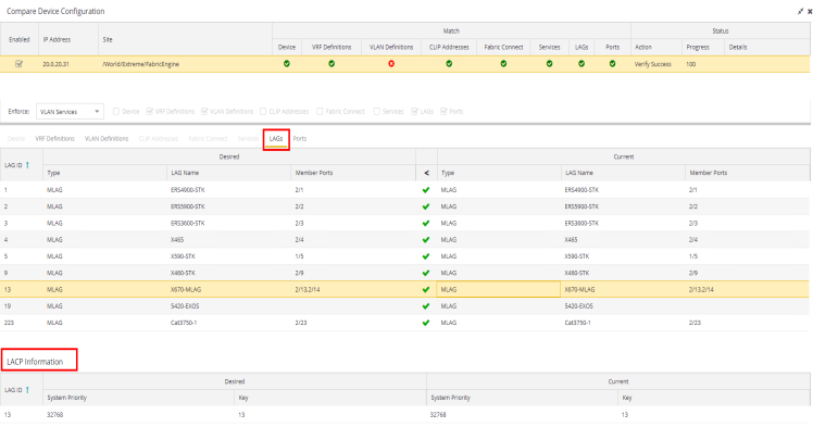
The LACP Information grid displays the following tabs, separated into Desired and Current columns:
- System Priority
- Displays the LACP priority, which ExtremeCloud IQ Site Engine uses to determine the probability network traffic uses the LAG. Valid values are between 1 and 65,535. The lower the value entered, the higher ExtremeCloud IQ Site Engine prioritizes the LAG.
- Key
- Displays the LACP key, which the LAG uses to ensure it only pairs with properly configured endpoints.
Ports
The Ports tab displays any changes to the configuration of ports on the device.
- Port
- The name of the port, constructed of the name or IP address of the device and either the port index number or the port interface name.
- Tagged
- The port is added to the list with the egress state set to Tagged (frames are forwarded as tagged).
- Untagged
- The port is added to the list with the egress state set to Untagged (frames are forwarded as untagged).
- Fabric Enable
- Indicates the fabric functionality is enabled on the port.
ExtremeCloud IQ Site Engine can extend FA functionality to ExtremeXOS/Switch Engine devices and provision them as FA Proxy devices. Select "Fabric Attach" or "" from the drop-down list to enable the port on a VOSS/Fabric Engine device (acting as FA Server) to connect to an ExtremeXOS/Switch Engine device (acting as FA Proxy).- Fabric Attach - Enable Fabric Attach server functionality on the port of a VOSS/Fabric Engine device acting as a Fabric Attach server) to connect to an ExtremeXOS/Switch Engine device (acting as a Fabric Attach proxy).
- Fabric Attach and Switched UNI - Enable Fabric Attach server functionality on the port of a VOSS/Fabric Engine device acting as a Fabric Attach server) to connect to an ExtremeXOS/Switch Engine device (acting as a Fabric Attach proxy). When selecting this option, the port is configured for both features, but only one feature is active at any one time.
- Auto Sense - Select Auto Sense on the port of a VOSS/Fabric Engine device to enable the port to automatically sense and configure automatically sense and configure the appropriate Fabric settings for the port. These settings include the following:
- PVID
- VLAN Trunk
- Tagged
- Untagged
- Fabric Mode
- Fabric Auth Type
- Fabric Auth Key
- Fabric Connect Drop STP-BPDU
- BPDU Guard
- Authentication
NOTE: If Fabric Enable is Auto Sense the Fabric settings listed above are not configurable.
- Fabric Auth Type
- If Fabric Enable is Fabric Attach or NNI, this defines the type of authentication the device uses for the port to communicate with the other ISIS devices to secure those services.
- Span Guard
- Select to enable Span Guard, which allows the device to shut down a network port if it receives a BPDU (bridge protocol data unit). Enable this feature on network edge ports to prevent rogue STA-aware devices from disrupting the existing Spanning Tree.
- SLPP
- Indicates Simple Loop Prevention Protocol (SLPP) is enabled on the port. SLPP provides active protection against Layer 2 network loops on a per-VLAN basis. If an SLPP packet is received, the port is disabled for the amount of time configured in the SLPP Timer field.
NOTE: If SLPP is enabled, SLPP Guard is not available.
- SLPP Guard
- Indicates whether SLPP Guard is enabled on the port. Use SLPP Guard to provide additional loop protection to protect wiring closets from erroneous connections. SLPP Guard requires SLPP to be enabled. SLPP detects loops in an SMLT network. Because SMLT networks disable Spanning Tree (STP), Rapid Spanning Tree (RSTP), or Multiple Spanning Tree Protocol (MSTP) for participating ports, SLPP Guard provides additional network loop protection, extending the loop detection to individual edge access ports. SLPP Guard can be configured on MLT or LAG ports. If the edge switch with SLPP Guard enabled receives an SLPP-PDU packet on a port, SLPP Guard operationally disables the port for the configured timeout interval in the SLPP Guard Timer field and appropriate log messages and SNMP traps are generated. If the disabled port does not receive any SLPP-PDU packets after the configured timeout interval expires, the port automatically re-enables and generates a local log message, a syslog message, and SNMP traps, if configured.
NOTE: If SLPP Guard is enabled, SLPP is not available
- SLPP Guard Timer
- Indicates the amount of time after receiving an SLPP packet before the port is re-enabled.
The Port VLAN Details grid opens at the bottom of the Device Configuration table: 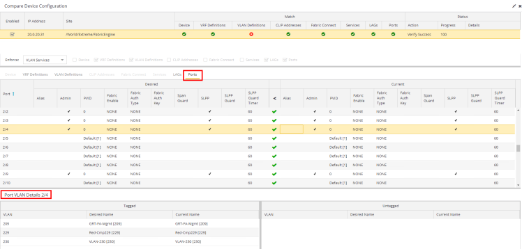
The Port VLAN Details grid displays desired and current ports, separated into Tagged and Untagged columns.
Select Enforce to save your changes to the device.
For information on related help topics:
![]()