Use this window to configure information for an existing device. From this window you can edit basic information about the device, the device annotation, configure actions for the device, add or remove ports for the device, and configure VLANs for the device.
To access this window:
- Open the Network > Devices tab.
- Select the Devices sub-tab.
- Select the Menu icon (
 ) or right-click on a device.
 - Select Device > Configure Device.
This window is also accessible by selecting the Configure Device button on the Discovered and Site tabs.
When you first open the window, the Device tab opens.
The Configure Device window contains the following tabs:
- Device
- Device Annotation
- VRF Definition
- VLAN Definition
- CLIP Addresses
- Fabric Connect
- Services
- LAG
- Ports
- ZTP+ Device Settings
- Flow Sources
- Vendor Profile
Additionally, Buttons at the bottom of the window allow you to perform different actions.
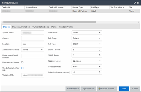
Device
The Device tab displays basic information about the device.
- System Name
- The system name of the device. This is displayed in the Network > Devices tab tree when Device Tree Name Format is set to System Name in the Local Settings window.
- Contact
- Allows you to specify contact information for the person maintaining the device. Additionally, enter a backslash "/" between contacts to create a device group in a tiered tree structure. For example, to move the device into a device group called "John's Devices" within a device group called "Quality Assurance Testing", enter Quality Assurance Testing/John's Devices in this field.
- Location
- The physical location of the device. Additionally, enter a backslash "/" between locations to create a device group in a tiered tree structure. For example, to move the device into a device group called "London" within a device group called "Europe", enter Europe/London in this field.
- Administration Profile
- Use the drop-down list to select the access profile that gives the Discover tool administrative access to the devices you wish to discover. To create
or edit a profile, use the Profiles tab.
- Replacement Serial Number
- Enter the number of the device replacing this device if Remove from Service is selected. When entered, ExtremeCloud IQ Site Engine restores the most recent archive of the device removed from service.
- Remove from Service
- Select this check box if the device is being removed from the network. ExtremeCloud IQ Site Engine will continue to monitor the device when Remove from Service is selected. When a replacement device is ready, continue the RMA process by adding the replacement device's serial number, shutting down the device to be removed, and starting the replacement device.
NOTE: A complete list of devices for which Remove from Service is selected is available via the Removed from Service Devices report on the Reports tab.
- Use Default WebView URL
- Select the check box to use the default WebView URL to access the device. The default WebView URL is provided by ExtremeCloud IQ Site Engine based on the vendor profile configured for the device.
- WebView URL
- Enter the WebView URL you want to use to access the device, if you do not want to use the default WebView URL.
NOTES: The option for editing the device Web View URL is available only after the device is onboarded to ExtremeCloud IQ Site Engine.
When modifying a device for the first time, the WebView URL is the default http://%IP. The %IP macro is replaced with the device's actual IP when Launch WebView is attempted.
If the %IP macro is present in the default WebView URL, it will be replaced with the device's actual IP Address when WebView is attempted.
For bulk edits on multiple devices, a valid WebView URL with the %IP macro is mandatory, so that %IP macro can be replaced with the actual IP Address of the device on which the WebView was attempted.
REST calls to the device will use the protocol (HTTP/HTTPS) and port configured in the WebView URL.
For ExtremeXOS/Switch Engine devices, the default WebView URL ( http://%IP%) instructs ExtremeCloud IQ Site Engine to use HTTP to communicate with the device. You must override the default WebView URL to communicate with the device via HTTPS, and optionally include a non-standard port (for example, https://%IP%:8443 - where 8443 is the non-standard port number in use).
- Default Site
- Use the drop-down list to select the map to which the device is associated. For additional information, see the Maps Overview topic.
- Poll Group
- Use the drop-down list to select a Poll Group for the discovered
devices. ExtremeCloud IQ Site Engine provides three distinct poll groups (configured in the
Status Polling view of the
Options tab) that each specify a unique poll frequency. When you save
newly discovered devices to the database, they are polled with the
poll group specified here. If you save discovered devices that already
exist in the database, the poll group specified here overwrites the
poll group currently being used in the database.
NOTE: Poll Group is not used if you set the Poll Type to Not Polled. To use Poll Group, select a Poll Type other than Not Polled.
- Poll Type
- Use the drop-down list to select the Poll Type for devices:
- Select Not Polled if you do not want to poll the devices.
- Select Ping for the Poll Type if the Profile for the IP Range is also set to Ping.
NOTE: On a Windows platform, device operational status cannot be determined for devices with their Poll Type set to Ping unless you are logged on and running ExtremeCloud IQ Site Engine as a user with Administrative privileges. - Select SNMP to poll the device using SNMP. The SNMP
version (SNMPv1 or SNMPv3) is determined by the Profile
specified for the IP Range.
- Select Maintenance if you do not want to poll the devices temporarily. Using this Poll Type allows you to search for devices set to Maintenance to change them back to their regular Poll Type after maintenance on the device is complete.
- Select ZTP+ for devices managed by ZTP+ and created through the ZTP+ process. When the Poll Type is ZTP+, ExtremeCloud IQ Site Engine does not initiate a poll, instead ExtremeCloud IQ Site Engine receives a message from the device or Fabric Manager messages to determine the status.
For example, if ExtremeCloud IQ Site Engine does not receive a message from a device or Fabric Manager for three times the amount of time defined in the Poll Interval for the Poll Group of the device, then the Status is Contact Lost. When ExtremeCloud IQ Site Engine receives a message from the device, the Device Status is Contact Established. - Status Only indicates a device for which you only need to monitor its status. This Poll Type is only displayed if the device was configured as Status Only when first added to ExtremeCloud IQ Site Engine.
The default polling interval for Status Only devices occurs every 12 hours and is configured in the Status Only Poll Interval field on the Administration > Options > Status Polling tab. Status Only devices do not support check box of statistics, FlexViews, Network Status Monitor, or enforcement via ExtremeCloud IQ Site Engine. You can add a maximum of 10,000 Status Only devices in ExtremeCloud IQ Site Engine, which do not count against your licensed device limit.NOTE: You cannot change the Poll Type of an existing device to Status Only. To change the Poll Type of a device that currently exists in ExtremeCloud IQ Site Engine to Status Only, delete the device, add the device in ExtremeCloud IQ Site Engine via the Add Devices window, and select the Poll Status Only check box.
The options available in the Poll Type drop-down list vary depending on the method used to add the device:
- If device is added via ZTP+, Not Polled, Ping, SNMP, Maintenance, and ZTP+ are available as Poll Type options. After changing the Poll Type to an option other than ZTP+, ZTP+ is no longer be available. To select ZTP+, delete the device and add it via the ZTP+ process.
- If device is added using SNMP, Not Polled, Ping, SNMP, and Maintenance are available as Poll Type options.
- If device is added using Ping, Not Polled, Ping, SNMP, and Maintenance are available as Poll Type options.
- If device is added as Status Only (Ping or SNMP), then Poll Group and Poll Type options are not available.
Select the check box to use the global SNMP settings values from Administration > Options > SNMP > Configuration for the device.
When enabled, the SNMP Timeout and SNMP Retries fields and values are disabled.
- SNMP Timeout
- The amount of time that ExtremeCloud IQ Site Engine waits before re-trying to
contact the device. The value for this setting must be between 1 and 60 seconds.
The Use Global SNMP Settings must be disabled for the SNMP Timeout value to apply to the device.NOTE: When SNMP requests are redirected through the server, all SNMP timeouts are extended by a factor of four (timeout X 4) to allow for the delays incurred by redirecting requests through the server.
- SNMP Retries
- The number of attempts ExtremeCloud IQ Site Engine makes to contact a device after an attempt at contact fails. The value for this setting must be between 0 and 10 tries.
The Use Global SNMP Settings must be disabled for the SNMP Retries value to apply to the device.
- Collection Mode
- Select None, Threshold Alarms, or Historical from the check box Mode drop-down menu to indicate the mode to collect device statistics.
- Collection Interval (minutes)
- Select the interval at which device and statistics are collected. Extreme sets a minimum check box interval of five minutes and a maximum of 1440 minutes (24 hours).
Device Annotation
The Device Annotation tab allows you to add user-defined information about the device. Asset tag, User Data 1-4, and Device Note information saved on this tab is shared with ExtremeCloud IQ.
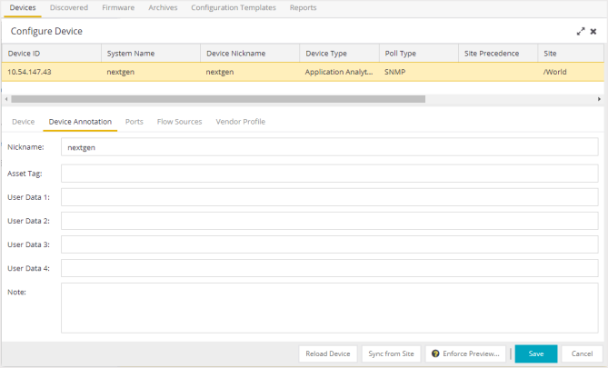
- Nickname
- The user-defined nickname for the selected device. The device nickname, which is used only by ExtremeCloud IQ Site Engine and is not stored on the device, displays when you select Nickname in the Name Format section on Administration > Options tab.
- User Data
- The user-defined information displayed in the devices table in the User Data columns. Additionally, enter a backslash "/" between user data to create a device group in a tiered tree structure. For example, to move the device into a device group called "Dorm 1" within a device group called "Campus", enter Campus/Dorm 1 in this field.
VRF Definition
The VRF Definition tab allows you to configure VRFs on the device. To add a VRF, select the Add button. You can remove a VRF by selecting the Delete button.
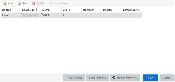
- Source
- Indicates the location from which the VRF is inherited. The VRF can be inherited from a site, locally configured on the device itself, or can be excluded.
NOTE: Selecting Exclude indicates you are excluding an inherited configuration. VRF configurations locally defined on the device and are not cannot be excluded. You can only select Exclude for configurations inherited from a Site (or a Service Application).
- Direct Route
- Select to indicate the service sends IP packets directly to another device without going through a third device.
VLAN Definition
The VLAN Definition tab allows you to configure VLANs on the device.
The VLAN Definition tab also has the following buttons:
- Add - Use this button to add a VLAN.
- Add Range - Use this button to add VLANs in a group instead of manually adding and editing one entry at a time. For more information, see Fabric Assist.
- Edit - Use this button to you to change the configuration of a VLAN.
- Delete - Use this button to remove a VLAN.
- Enable Pruning - Use this button to prevent VLANs with no egress from being enforced to a device. For more information, see Fabric Assist.
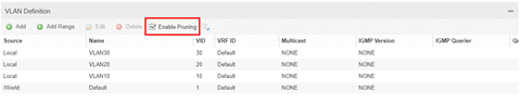
- Source
- Indicates the location from which the VLAN is inherited. The VLAN can be inherited from a site, locally configured on the device itself, or can be excluded.
NOTE: Selecting Exclude indicates you are excluding an inherited configuration. VLAN configurations locally defined on the device and are not cannot be excluded. You can only select Exclude for configurations inherited from a Site (or a Service Application).
- VID
- Indicates the VLAN ID for the VLAN. A unique number between 1 and 4094 that identifies a particular VLAN. VID 1 is reserved for the Default VLAN.
- IGMP Version
- Indicates which version of IGMP is utilized on the port (Version 1 or Version 2).
- IGMP Querier
- Indicates whether the device has sent IGMP queries to solicit VLAN membership information from other devices.
- Virtual Routing
- Displays the version of VRRP the default gateway is using:
- NONE — Virtual routing is not configured on the VLAN.
- VRRPv2 — VRRP version 2 is configured on the VLAN. VRRP version 2 only supports IP addresses in IPv4 format.
- VRRPv3 — VRRP version 3 is configured on the VLAN. VRRP version 3 supports IP addresses in both IPv4 and IPv6 formats.
- DvR — DvR is configured on the VLAN. There are several requirements that must be met to configure DvR on a VLAN, including:
- The VLAN must have an IP address and prefix.
- The DvR IP address must be IPv4.
- The DvR IP address must fall within the VLAN's subnet.
- The DvR IP address cannot be reused across multiple VLANs on the device.
- The VLAN must have an L2VSN associated with it.
- If the VLAN is using on a non-zero VRF ID, the VLAN must also have:
- An L3VSN associated with the VRF.
- The VRF must have the unicast option enabled.
- Devices participating in DvR as controllers must have non-zero IPv4 ISIS Source Addresses.
- Devices participating in DvR must have IPv4 Shortcuts and Multicast enabled.
- RSMLT — Routing Redundancy Method is configured on the VLAN. RSMLT requires that a Virtual IST is configured. If the device is not configured as a vIST pair, RSMLT can be selected, but the feature is not active. Once the vIST is configured, RSMLT becomes active.
NOTES : Virtual Routing is only supported on Fabric Engine devices.
Fabric Engine devices support a new "dvr-one-ip" feature in the 8.2 release that allows you to share an IP address between a VLAN and its DvR interface. ExtremeCloud IQ Site Engine currently does not support the "dvr-one-ip" feature and cannot read or enforce configurations of this type. Configure Fabric Engine device IP addresses on VLANs and their DvR interfaces through the VLAN Definitions tab.
- Virtual Routing Address
- The IP address for the virtual routing interface. The Virtual Routing address must be in the same subnet as the VLAN subnet address.
- VRRP ID
- An identifier devices use to determine peer devices that participate in a VRRP (Virtual Routing Redundancy Protocol) virtual routing interface.
- VRRP Priority
- A value used by VRRP peers to determine the role of each of the devices in the VLAN. The default value is 100. The device with the largest value is assigned the role of Controller. For example, in a VLAN with two routers, one with a VRRP Priority of 200 and one with a VRRP Priority of 100, the router with a VRRP Priority of 200 becomes the Controller. In the event of identical priority numbers, the devices use the MAC address to determine priority.
- VRRP Backup Master
- This option determines if the backup router is able to forward traffic independently outside of the VLAN (enabled), or must forward the traffic to the Controller router before it is forwarded outside of the VLAN (disabled).
- VRRP Advertisement Interval
- Indicates frequency (in seconds) that protocol packets are sent from the virtual router in the VLAN.
- VRRP Hold Down Timer
- Indicates the amount of time (in hundredths of a second) that the backup router waits for the primary router to respond before it becomes the primary router.
- DHCP Relay
- Indicates whether a Dynamic Host Configuration Protocol relay server is enabled for the VLAN. A DHCP relay receives and converts a DHCP broadcast message to dynamically assign an IP address to a device on the network.
- DHCP Relay Servers
- The IP addresses of the DHCP relay servers for the VLAN.
NOTE: Select Manage to open the Manage DHCP Relay Servers window, where you can add or delete DHCP relay servers.
- DHCP Snooping
- Indicates whether DHCP snooping is enabled for the VLAN. DHCP Snooping is a Layer 2 security feature, that provides network security by filtering untrusted DHCP messages received from the external network causing traffic attacks within the network. DHCP Snooping is based on the concept of trusted versus untrusted switch ports. Switch ports configured as trusted can forward DHCP Replies, and the untrusted switch ports cannot. DHCP Snooping acts like a firewall between untrusted hosts and DHCP servers.
- ARP Inspection
- Indicates whether ARP inspection is enabled. Dynamic ARP Inspection (DAI) is a security feature that validates ARP packets in the network. Without DAI, a malicious user can attack hosts, switches, and routers connected to the Layer 2 network by poisoning the ARP caches of systems connected to the subnet, and intercepting traffic intended for other hosts on the subnet. DAI prevents these attacks by intercepting, logging, and discarding the ARP packets with invalid IP to MAC address bindings. The switch dynamically builds the address binding table from the information gathered from the DHCP requests and replies when DHCP Snooping is enabled. The switch pairs the MAC address from the DHCP request with the IP address from the DHCP reply to create an entry in the DHCP binding table. When you enable DAI, the switch filters ARP packets on untrusted ports based on the source MAC and IP addresses seen on the switch port. The switch forwards an ARP packet when the source MAC and IP address matches an entry in the address binding table. Otherwise, the switch drops the ARP packet.
NOTE: DHCP Snooping must be enabled to use ARP Inspection.
CLIP Addresses
Use the CLIP Addresses tab to add, edit or delete IPv4 and IPv6 CLIP Addresses to your device.
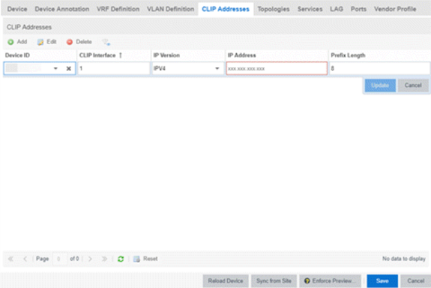
| NOTE: |
To use the CLIP address on non-DVR Leaf the "IP Shortcuts" must be enabled. To use the CLIP address on DVR Leaf the "IP Shortcuts" must be disabled. "IP Shortcuts" can be enabled or disabled from the Fabric Connect > Fabric Features tab or the assigned Topology Definition. |
|---|
Fabric Connect
The Fabric Connect tab allows you to select and configure Fabric Connect features to devices in your network.
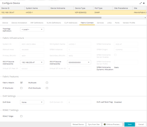
- Topology Definition
- Select the Topology Definition that applies to the device. The Topology Definitions available in the drop-down list are configured in the Topology Definition tab.
- None - No Fabric Connect configuration on the device. If you select None for a device that is configured for Fabric Connect, that configuration is removed from ExtremeCloud IQ Site Engine when you select Save, and from the device when you enforce the change.
- Local - ExtremeCloud IQ Site Engine uses the Fabric Connect settings configured locally to enforce to the device.
- Disabled - The Fabric Connect configuration is applied to the device, but ISIS is disabled, which allows the user to take a device out of service without removing all its configuration.
- Topology Definition - The Topology Definition that has been specified for the site to which the device is assigned.
- System ID
- The system-defined fabric service identifier assigned to the device. The default is the MAC address for the device. This field is editable only if Topology Definition is disabled.
- Manual Area
- The IS-IS Manual Area in xx.xxxx.xxxx.xxxx.xxxx.xxxx.xxxx format (1-13 bytes). This information is configured on the Sites > Topology Definition tab. This field is editable only if Topology Definition is disabled.
- Primary BVLAN
- The Primary Backbone VLAN. This information is configured on the Sites > Topology Definition tab. This field is editable only if Topology Definition is disabled.
- ISIS IP Source Address (V4)
- The IPv4 address the device uses to transmit ISIS traffic to other fabric devices. The address must be unique within the fabric. This field is editable when Topology Definition is set to either Local or Disable, or a user-defined topologydefinition.
- Virtual IST Peer IP
- Virtual InterSwitch Trunk (IST) provides the ability to dual-home hosts, servers, and other network devices to a pair of Multi-Chassis Link Aggregation (MC-LAG) enabled devices. Virtual IST creates a virtualized channel through the SPBM cloud, and this channel connects two SMLT devices to form a virtualized cluster. The peer IP address identifies the other peers. It cannot be edited from this interface.
- ISIS System Name
- The system name of the device. This field is editable only if Topology Definition is disabled.
- SPBM Instance
- The system-defined identifier for the Fabric Connect configuration on the device. The default value is 1.
- Secondary BVLAN
- The Secondary Backbone VLAN. This information is configured on the Sites > Topology Definition tab. This field is editable only if Topology Definition is disabled.
- ISIS IP Source Address (V6)
- The IPv6 address the device uses to transmit ISIS traffic to other fabric devices. The address must be unique within the fabric. This field is editable when Topology Definition is set to either Local or Disable, or a user-defined Topology Definition.
- Virtual IST VLAN ID
- Virtual IST provides the ability to dual-home hosts, servers, and other network devices to a pair of MC-LAG enabled devices. Virtual IST creates a virtualized channel through the SPBM cloud, and this channel connects two SMLT devices to form a virtualized cluster. The VLAN ID identifies the communication channel between the peers. It cannot be edited from this interface.
- SPBM Nickname
- A value that other fabric devices use to identify the device. The SPBM Nickname must be unique within the fabric. This field is editable only if Topology Definition is disabled.
- SPBM Origin
- This field indicates the source of the SPBM configuration because it cannot be added from ExtremeCloud IQ Site Engine. If it is set to Config, it means the device is the source of the SPBM configuration. If it is set to Dynamic, it means that the SPBM configuration was provided via AutoSense.
- SPBM Nickname Server Enable
- This enables a Fabric Engine device to behave like a the Nickname Server. You can enable this function when Topology Definition is set to Local, Disable, or a user-defined topology definition, and SPBM Nickname Dynamic Allocation is set to Dynamic.
- SPBM Nickname Server Prefix
- Set the prefix for the Nickname Server. This is the 1-byte "x.y" portion of the larger "1.23.45" nickname format. This field can be edited when SPBM Nickname Server Enable is selected and the Topology Definition is Local, Disable, or a user-defined topology definition.
- SPBM Nickname Dynamic Allocation
- This field indicates where the device SPBM Nickname came from because it cannot be added from ExtremeCloud IQ Site Engine. Static means the SPBM Nickname was manually assigned by the user. Dynamic means the SPBM Nickname was allocated dynamically from another fabric node operating as an SPBM Nickname Server.
- Fabric Attach
- Select the check box to enable Fabric Attach server functions on a Fabric Connect device. Deselect the check box to disable Fabric Attach server functions.
NOTE: You can enable Fabric Attach on the following devices: Fabric Engine, ERS 49xx v5.9.2 and later, ERS 4850 v5.9.2 and later, and ERS 59xx series devices
- Multicast
- Select the check box to enable Multicast for the device.
- DvR Role
- Select the DvR Role from the drop-down list:
- None - DvR (Distributed Virtual Routing) is not configured on the device.
- Controller - Indicates the device is one of the main devices participating in the DvR virtual routing interface.
- Leaf - Indicates the device is one of several edge devices within the DvR domain. DvR Role as Leaf requires the DvR Leaf Boot Flag Enabled.
- Global Backbone - Indicates the device is a standard Fabric Connect device and does not run the DvR protocol, but learns routes from DvR controllers in the fabric.
- DvR Leaf Boot Flag
- Indicates the DvR Leaf Boot Flag setting for the device. If the boot flag is Enabled, the DvR Role can be None or Leaf. If the boot flag is Disabled, the DvR Role can be None, Controller, or Global Backbone.
-
NOTE: You can use the system workflow to enable or disable the DvR Leaf Boot Flag for Fabric Engine Release 8.4 and earlier.
- RSMLT Edge
- Select this option to use the RSMLT Edge.
Services
The Services tab displays the services created within service applications and configured on the device. Use this tab to add new services to the device. Services may be inherited from a service definition or may be configured locally on the device.
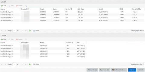
L2 VSN
- The User-Network-Interface (UNI) of the fabric service. The following interface types are available:
-
- Switched — A VLAN-ID and a port (VID, port) mapped to a Layer 2 VSN I-SID. With UNI type, VLAN-IDs can be reused on other ports and mapped to different ISIDs.
- Transparent - A physical port maps to a Layer 2 VSN I-SID (all traffic through the port, 802.1Q tagged or untagged, ingress and egress maps to the I-SID).
- CVLAN — a platform customer VLAN-ID
NOTE: All VLANs on a Transparent Port UNI interface now share the same single MAC learning table of the Transparent Port UNI I-SID.
- AP Untagged — If the AutoSense feature detects Access Point, then this service is automatically assigned to the port.
- Camera Untagged — If the AutoSense feature detects Camera then this service is automatically assigned to the port.
- Voice Untagged — If the AutoSense feature detects a VoIP device then this service is automatically assigned to the port.
- Voice Tagged — If the AutoSense feature detects a VoIP device then this service is automatically assigned to the port.
- Proxy Switch Auth Tagged — If the AutoSense feature detects a Fabric Attach switch capable of authenticating (ERS devices) then this service is automatically assigned to the port.
- Proxy Switch No Auth Untagged — If the AutoSense feature detects a Fabric Attach switch is not capable of authenticating (Switch Engine devices) then this service is automatically assigned to the port.
- Proxy Switch Auth & Proxy Switch No Auth — If the AutoSense feature detects any physical Fabric Attach switch (ERS/EXOS/Switch Engine device) then this service is automatically assigned to the port.
- Data Untagged — If the AutoSense feature does not detect a device type then this service is automatically assigned to the port.
- None — AutoSense is not related to this L2VSN service.
| NOTE: |
Each AutoSense Service Type can only be used once on a switch. The switch cannot use two different service IDs with the same AutoSense Service Type. |
L3 VSN
LAG
Use the LAG tab to configure LAGs and MLAGs (also known as MLTs and SMLTs, respectively). A LAG combines multiple network connections to increase the throughput beyond that of a single connection. An MLAG allows a device to send network traffic to two switches to improve network diversity, while only managing a single logical interface.
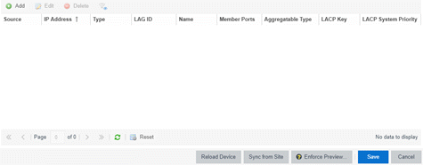
- Source
- Indicates the location from which the LAG is inherited. The LAG can be inherited from a site, locally configured on the device itself, or can be excluded.
NOTE: Selecting Exclude indicates you are excluding an inherited configuration. LAG configurations locally defined on the device and are not cannot be excluded. You can only select Exclude for configurations inherited from a Site (or a Service Application).
- Aggregatable Type
- Indicates whether the LAG is static or dynamic:
- Static — the LAG is static.
- LACP — the LAG is dynamic via LACP.
- LACP Key
- Displays the LACP key, which the LAG uses to ensure it only pairs with properly configured endpoints.
- LACP System Priority
- Displays the LACP priority, which ExtremeCloud IQ Site Engine uses to determine the probability network traffic uses the LAG. Valid values are between 1 and 65,535. The lower the value entered, the higher ExtremeCloud IQ Site Engine prioritizes the LAG.
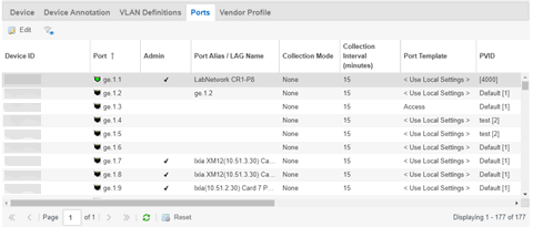
Ports
The Ports tab allows you to edit information about the ports on a device.
- Name
- Enter the name of the port, constructed of the name or IP address of the device and either the port index number or the port interface name.
- Auto Negotiation
- Displays whether auto negotiation is enabled or disabled on the port. If Auto Negotiation is enabled, multi-speed selections are enabled.
- Speed
- Displays the current speed of the selected port. Use the drop-down list to select the speed if auto negotiation is enabled on the port.
- Duplex
- Displays the current duplex mode for the selected port. Use the drop-down list to select the mode if auto negotiation is enabled on the port.
- Collection Mode
- Indicates the collection mode (Historical, Threshold Alarms, or None) which has been configured on the Administration > Options > ExtremeCloud IQ Site Engine Collector > Port Collection field, for port statistics collected for ports.
- Collection Interval (minutes)
- Indicates the frequency (in minutes) at which port statistics are collected. The poll interval is configured on the Administration > Options > ExtremeCloud IQ Site Engine Collector > Port Collection tab. The default poll interval set by ExtremeCloud IQ Site Engine is 15 minutes.
- Port Template
- Use the drop-down list to select a Port Template you define on the Site tab. Adding a device to a site allows you to select from the Port Templates defined for that site:
- <Use Local Settings> — Select this option if you do not want the port to inherit any settings from any defined Port Template.
- Access — Select this option if the port connects to user end-systems.
- Interswitch — You can also manually select this option if the port is used to connect to other switches. This option is selected by default if the port detects neighboring switches are configurable.
- Management — Select this option if the port is used to manage network traffic with ExtremeCloud IQ Site Engine.
- AP — Select this option if the port is used to connect with a networking device that allows a Wi-Fi device to connect to a wired network.
- Phone — Select this option if the port is used to connect to a telephone.
- Router — Select this option if the port is used to connect to a router.
- Printer — Select this option if the port is used to connect to a printer.
- Security — Select this option if the port is used to connect to a device or devices that have been configured with security or advanced security settings.
- IoT — Select this option if the port is used to connect to an additional wireless"smart" device.
- Other — Select this option if the port is used to connect to any other device.
- PVID
- Select the port's VLAN ID.
- Authentication
- Use the drop-down list to determine whether authentication is required to access the port:
- None — No authentication is required to access the port.
- 802.1X — Select this option to require 802.1X authentication to access the port.
- MAC Auth — Select this option to require authentication based on the users MAC address.
- VLAN Trunk
- Automatically configures a port as a VLAN trunk when you check one box in the VLAN Trunk column. For more information, see Fabric Assist.
- Tagged
- Indicates the port's egress state is tagged. If you check the VLAN Trunk column, Fabric Assist automatically configures all the VLANs on the port as tagged. For more information, see Fabric Assist.
- Fabric Enable
- Indicates the fabric functionality is enabled on the port.
ExtremeCloud IQ Site Engine can extend FA functionality to ExtremeXOS/Switch Engine devices and provision them as FA Proxy devices. Select "Fabric Attach" or "" from the drop-down list to enable the port on a Fabric Engine device (acting as FA Server) to connect to an ExtremeXOS/Switch Engine device (acting as FA Proxy).- Fabric Attach - Enable Fabric Attach server functionality on the port of a Fabric Engine device acting as a Fabric Attach server) to connect to an ExtremeXOS/Switch Engine device (acting as a Fabric Attach proxy).
- Fabric Attach and Switched UNI - Enable Fabric Attach server functionality on the port of a Fabric Engine device acting as a Fabric Attach server) to connect to an ExtremeXOS/Switch Engine device (acting as a Fabric Attach proxy). When selecting this option, the port is configured for both features, but only one feature is active at any one time.
- Auto Sense - Select Auto Sense on the port of a Fabric Engine device to enable the port to automatically sense and configure automatically sense and configure the appropriate Fabric settings for the port. These settings include the following:
- PVID
- VLAN Trunk
- Tagged
- Untagged
- Fabric Mode
- Fabric Auth Type
- Fabric Auth Key
- Fabric Connect Drop STP-BPDU
- BPDU Guard
- Authentication
NOTE: If Fabric Enable is Auto Sense the Fabric settings listed above are not configurable.
- Node Alias
- Select to enable the node alias function on the port. The node alias settings are automatically enabled if Access Control is enabled on the device.
- Span Guard
- Select to enable Span Guard, which allows the device to shut down a network port if it receives a BPDU (bridge protocol data unit). Enable this feature on network edge ports to prevent rogue STA-aware devices from disrupting the existing Spanning Tree.
- Loop Protect
- Select to prevent loop formation in a network with redundant paths by requiring ports to receive type 2 BPDUs (RSTP/MSTP) on point‐to‐point interswitch links.
- If the ports receive the BPDUs, the link's State becomes Forwarding.
- If a BPDU timeout occurs on the ports, its state becomes listening until a BPDU is received.
- MVRP
- Indicates that the Multiple VLAN Registration Protocol (MVRP) has been enabled for the port. If MVRP has been enabled globally, interswitch ports are automatically enabled and access ports default to disabled.
- SLPP
- Indicates Simple Loop Prevention Protocol (SLPP) is enabled on the port. SLPP provides active protection against Layer 2 network loops on a per-VLAN basis. If an SLPP packet is received, the port is disabled for the amount of time configured in the SLPP Timer field.
NOTE: If SLPP is enabled, SLPP Guard is not available.
- SLPP Guard
- Indicates whether SLPP Guard is enabled on the port. Use SLPP Guard to provide additional loop protection to protect wiring closets from erroneous connections. SLPP Guard requires SLPP to be enabled. SLPP detects loops in an SMLT network. Because SMLT networks disable Spanning Tree (STP), Rapid Spanning Tree (RSTP), or Multiple Spanning Tree Protocol (MSTP) for participating ports, SLPP Guard provides additional network loop protection, extending the loop detection to individual edge access ports. SLPP Guard can be configured on MLT or LAG ports. If the edge switch with SLPP Guard enabled receives an SLPP-PDU packet on a port, SLPP Guard operationally disables the port for the configured timeout interval in the SLPP Guard Timer field and appropriate log messages and SNMP traps are generated. If the disabled port does not receive any SLPP-PDU packets after the configured timeout interval expires, the port automatically re-enables and generates a local log message, a syslog message, and SNMP traps, if configured.
NOTE: If SLPP Guard is enabled, SLPP is not available
- SLPP Guard Timer
- Indicates the amount of time after receiving an SLPP packet before the port is re-enabled.
- DHCP Snooping
- Specifies the trust factor of the port for DHCP Snooping. The agent at the switch determines if DHCP reply packets are forwarded based on the DHCP Snooping mode of the VLAN and the trusted state of the port. If the value is "Trusted", the agent trusts the device on the port. If the value is "Untrusted", the agent does not trust the device on the port.
- ARP Inspection
- Dynamic ARP Inspection (DAI) is a security feature that validates ARP packets in the network. Without DAI, a malicious user can attack hosts, switches, and routers connected to the Layer 2 network by poisoning the ARP caches of systems connected to the subnet and intercepting traffic intended for other hosts on the subnet. DAI can prevent attacks by intercepting, logging, and discarding the ARP packets with invalid IP to MAC address bindings. The switch dynamically builds the address binding table from the information gathered from the DHCP requests and replies when DHCP Snooping is enabled. The switch pairs the MAC address from the DHCP request with the IP address from the DHCP reply to create an entry in the DHCP binding table. Values are "Trusted" and "Untrusted".
- Source Guard
- IP Source Guard (IPSG) is a Layer 2 port-to-port feature that works closely with DHCP Snooping. IPSG can prevent IP spoofing by allowing only IP addresses obtained using DHCP Snooping. When you enable IPSG on an untrusted port with DHCP Snooping enabled, an IP filter is automatically created or deleted for that port based on the information stored in the corresponding DHCP Snooping binding table entry. When a connecting client receives a valid IP address from the DHCP server, the filter installed on the port allows traffic only from that assigned IP address. If the value is "Disabled" the Source Guard is disabled. If the value is "IP" the IP Source Guard feature is enabled.
- VPEX Type
- Indicates how this port is used to connect a port extender to a controlling bridge or another port extender:
- Cascade — Traffic leaving this port is moving away from the controlling bridge.
- Uplink — Traffic leaving this port is moving toward the controlling bridge.
- None — The port is not included in connecting the extended bridge components.
NOTE: If the VPEX Type is Cascade or Uplink, you are unable to configure PVID, Tagged VLANs, and Untagged VLANs.
ZTP+ Device Settings
The ZTP+ Device Settings tab contains basic information about an existing device AFTER the device was discovered by ExtremeCloud IQ Site Engine via ZTP+.
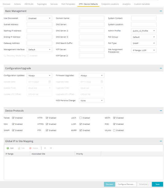
- Use Discovered
- Use the drop-down list to select if ExtremeCloud IQ Site Engine assigns the IP address, IP address and Management Interface, or Management Interface to the ZTP+ device when it is discovered:
- IP — ExtremeCloud IQ Site Engine uses the Discovered IP assigned when the device was discovered. Select the Management Interface (the VLAN interface used to manage the device) manually.
- IP and Management Interface — ExtremeCloud IQ Site Engine uses the Discovered IP and the Management Interface that were assigned when the device was discovered.
- Management Interface — ExtremeCloud IQ Site Engine uses the Management Interface that was defined when the device was discovered. Enter the IP address and subnet, Gateway Address, Domain Name, and DNS Server in the tab (along with any of the optional fields) and then save.
- Disabled — Configure the IP address and subnet, Gateway Address, Domain Name and DNS Server in the tab (along with any of the optional fields) and then save.
- Management Interface
- Select the interface the device uses for Management and assigns the device IP to that interface. Options are: VLAN, Out-Of-Band, Management Service, CLIP Address. If the option Management Service is selected, then one of the L2 VSN services must have Management Service selected, and the management IP applied to the Management Service. If the option CLIP Address is selected, then during the ZTP+ onboarding you should define the CLIP address in the GlobalRouter VRF, and mark it as Address Type MGMT. Then the MGMT CLIP address will be used for the switch management.
- CLI Recovery Mode Only
- Select the check box to disable the CLI account while the device is able to communicate with ExtremeCloud IQ Site Engine.
If connectivity between the device and ExtremeCloud IQ Site Engine is lost, the device enables the CLI account defined in the profile so the user can gain local access.
When connectivity between the device and ExtremeCloud IQ Site Engine is reestablished, the CLI account is disabled again.
NOTE: Only devices managed using ZTP+ support this functionality.
- Domain Name
- Enter a value in the Domain Name field to configure the domain name on the ZTP+ devices being discovered.
- DNS Server
- The DNS Server field allows you to set the DNS server address on the ZTP+ devices associated with the site.
- DNS Server 2
- The DNS Server 2 field allows you to set the secondary DNS server address on the ZTP+ devices associated with the site.
- DNS Server 3
- The DNS Server 3 field allows you to set the tertiary DNS server address on the ZTP+ devices associated with the site.
- DNS Search Suffix
- The DNS Search Suffix field allows you add additional comma-separated entries to DNS search suffix list configured on the device. Support for the DNS search suffix is dependent on the device operating system and version. Refer to your device specifications to determine the maximum number of entries that you can add.
- NTP Server
- The NTP Server field allows you to set the NTP server address on the ZTP+ devices being discovered.
- NTP Server 2
- The NTP Server 2 field allows you to set the secondary NTP server address on the ZTP+ devices associated with the site.
Configuration/Upgrade
- Configuration Updates
- Select the frequency for which ExtremeCloud IQ Site Engine checks for configuration updates for your ZTP+ enabled devices associated with the site.
- Update Date
- Select the date on which ExtremeCloud IQ Site Engine updates the configuration for your ZTP+ enabled devices associated with the site when you select Scheduled for Configuration Updates.
- Update Time
- Select the time at which ExtremeCloud IQ Site Engine updates the configuration for your ZTP+ enabled devices associated with the site when you select Scheduled for Configuration Updates.
- Update UTC Offset
- Select your time zone based on the number of hours you are offset from the Universal Time Coordinated.
- Firmware Upgrades
- Select the frequency for which ExtremeCloud IQ Site Engine checks for firmware upgrades for your ZTP+ enabled devices associated with the site.
- Upgrade Date
- Select the date on which ExtremeCloud IQ Site Engine upgrades the firmware for your ZTP+ enabled devices associated with the site when you select Scheduled for Firmware Upgrades.
- Upgrade Time
- Select the time at which ExtremeCloud IQ Site Engine upgrades the firmware for your ZTP+ enabled devices associated with the site when you select Scheduled for Firmware Upgrades.
- Upgrade UTC Offset
- Select your time zone based on the number of hours you are offset from the Universal Time Coordinated.
Device Protocols/Features
- HTTPS
- Select the check box to enable HTTPS (Hypertext Transfer Protocol Secure) access on the ZTP+ device.
NOTE: To enable HTTPS access, an SSL certificate must be configured on the device.
- SNMP
- Select the check box to enable SNMP (Simple Network Management Protocol) access on the ZTP+ device.
- LACP
- Select the check box to enable LACP (Link Aggregation Control Protocol) access on the ZTP+ device.
- MSTP
- Select the check box to enable MSTP (Multiple Spanning Tree Protocol) access on the ZTP+ device.
- MVRP
- Select the check box to enable MVRP (Multiple VLAN Registration Protocol) access on the ZTP+ device.
- POE
- Select the check box to indicate the ZTP+ devices being discovered for the site are electrically powered via the Ethernet cable.
- VXLAN
- Select the check box to indicate the ZTP+ devices being discovered for this site use VXLAN to tunnel Layer 2 traffic over a Layer 3 network.
NOTE: ZTP+ does not currently provision a Layer 3 network with which VXLAN operates. If your ZTP+ devices use VXLAN, the Layer 3 underlay network must be manually provisioned.
- DvR Leaf
- Select the check box to indicate the ZTP+ devices being discovered for the site operate in DvR Leaf mode. The DvR Leaf flag is enabled. Only devices running Fabric Engine support the DvR Leaf feature.
Flow Sources
The Flow Sources tab allows you to configure devices to act as flow sources for an ExtremeAnalytics engine.
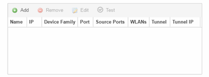
- Port
- Indicates the mirror port attached to the ExtremeAnalytics engine or used to create the GRE tunnel.
- Source Ports
- Displays the ports on which flow check box is enabled.
NOTE: Policy mirrors the first 15 packets of each flow received on the Source Ports to the ExtremeAnalyticsengine.
- WLANs
- Displays the WLANs of which the wireless controller being used as a flow source device is a member.
- Tunnel
- Indicates the device is configured to mirror flows using a GRE tunnel.
NOTE: If Tunnel is disabled, the ExtremeAnalytics engine must be directly attached to the flow source.
- Tunnel IP
- Displays the management IP address of the flow source device or the IP address of the loop-back interface on the device.
- Add
- Select Add to open a window from which you can select a device in ExtremeCloud IQ Site Engine to add as a flow source.
- Remove
- Select a flow source device in the table and select Remove to remove the device as a flow source.
- Edit
- Select Edit to open a window from which you can change the configuration of a flow source device.
- Test
- Select Test to verify the GRE tunnel end-points can communicate.
NOTE: Test is only available if Tunnel is enabled.
Vendor Profile
Use the Vendor Profile tab to determine how devices are identified in ExtremeCloud IQ Site Engine.
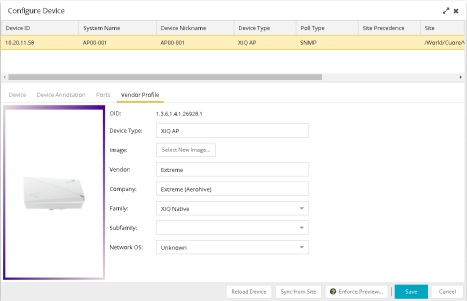
- Device Type
- Displays the specific type of device.
NOTE: When Device Type is blank: - ExtremeCloud IQ Site Engine cannot identify the device type, so the tab is named New Vendor Profile to allow you to optionally provide the device type details.
- If a device's Vendor is recognized, but ExtremeCloud IQ Site Engine does not have a profile for the device's unique OID, the Device Type, Family and Subfamily values are empty, but ExtremeCloud IQ Site Engine supplies the Vendor and Company values.
- If a Device Type is not recognized, and you leave the Device Type selection blank and subsequently upgrade to a version of ExtremeCloud IQ Site Engine with a Vendor Profile that recognizes the device type, ExtremeCloud IQ Site Engine supplies the properties of the Vendor Profile.
- If a Device Type is not recognized, and you customize the Device Type selection by entering the Device Type, Image, Vendor, Company, Family, Subfamily, and Network OS information, and subsequently upgrade to a version of ExtremeCloud IQ Site Engine with a Vendor Profile that recognizes the device type, the properties of the Vendor Profile are not updated and the customized device type data you entered is retained.
To remove all user-defined Vendor Profile configurations and restore the default system configurations provided with the installed version of ExtremeCloud IQ Site Engine, select the Restore to Defaults button on the Administration > Diagnostics > System > Vendor Profile Cache tab. Selecting the Restore to Defaults button removes your customizations and any unknown device types and replaces them with the provided vendor profile data. If vendor profile mapping data still does not exist, selecting the Restore to Defaults button changes your customizations to "Unknown" and retains any unknown device types as "Unknown." - You can use the drop-down menus to select the information or add it manually.
- You cannot use special characters when creating a new Device Type.
- Image
- Indicates the image used for the device in the Device View and Maps. Select the Select New Image icon to select a new image for the device type.
- Family
- Displays the group of devices to which the device belongs, known as the device family in ExtremeCloud IQ Site Engine.
- Network OS
- ExtremeCloud IQ Site Engine's classification of the Network Operating System installed on the device. This allows ExtremeCloud IQ Site Engine to provide the appropriate scripts and workflows on a device's Tasks submenu when the device's Network OS matches one of the Network Operating Systems defined for the script or workflow.
NOTE: ExtremeCloud IQ Site Engine displays Unknown for devices before their Network OS is determined via a script or workflow (for example, onboarding new devices or when Network OS Grouping has not been provided for the device type).
Buttons
- Read Device
- Select to read configuration information from the device to populate ExtremeCloud IQ Site Engine. Read Device reads the configuration (e.g. VLAN Definition, Ports, Port VLANs) from the device and reloads it in ExtremeCloud IQ Site Engine.
NOTE: Selecting Read Device removes all unsaved (or enforced) changes made in the VLAN Definition and Ports tabs and reloads the configuration from the device to those tabs.
- Enforce Preview
- Select to open the Compare Device Configuration window, from which you can view and compare your current configuration and the proposed new configuration. This window allows you to verify all of the changes you are making to your devices and then enforce those changes to the device. This button displays after making a change that affects the device.
- Sync from Site
- Select to copy the site's configuration from the site to ExtremeCloud IQ Site Engine's representation of the selected devices. The site's configuration will be applied to the device if the device is assigned to the same site. The site's configuration settings that will override the device's settings are: device, device annotation, VRF definitions, VLAN definition, Fabric Connect, services, LAGs, and ports.
- The Sync from Site feature applies the ZTP+ Device default settings (such as VRF definitions) if the ZTP+ Device confirmation dialog was set to Yes for the Sync from Site field.
- You can use the Enforce Preview button to decide whether to save the settings to the device. (Some ExtremeCloud IQ Site Engine settings, like poll group and administration profile, will not be enforced to the device.)
For information on related help topics:
![]()