Use the Sites tab to define configuration templates. ExtremeCloud IQ Site Engine applies these configuration templates to devices you add to a site in your network. You can also use the tab to discover new devices in the site via device discovery or by using ZTP+ functionality.
| NOTE: | When adding an ExtremeXOS/Switch Engine device in ExtremeCloud IQ Site Engine, enter the following commands in the device CLI:configure snmpv3 add community "private" name "private" user "v1v2c_rw" configure snmpv3 add community "public" name "public" user "v1v2c_rw" enable snmp access enable snmp access snmp-v1v2c disable snmp access snmpv3 |
The Sites tab is divided into multiple sections, which you can expand to display more information.
| NOTE: | To save your changes and other additional functions for a device included in the site, right-click on the device and select Configure Device from the drop-down list. The Configure Device window opens. Use the buttons at the bottom of the Configure Device window to save, sync settings from the site to the device's configuration, enforce changes to the device, and more. |
Access Network > Devices and select Sites from the left-panel drop-down list. The Sites Tree View opens, which includes the sites in your network, as well as Topology Definitions and Service Definitions tabs.
Right-click the Topology Definitions tab to create topology or LAG (link aggregation group) topology definitions. Right-click the Service Definitions tab to create service definitions. The topology, LAG and service definitions are used to create the templates that build Fabric technology.
Select a site from the left-panel Sites Tree View. A tab in the Devices window opens with the name of the site you selected. To create a new site, click the menu icon in the left-panel and select Maps/Sites > Create Site.
The Site Name tab contains the following tabs:
- Discover
- Actions
- VRF/VLAN
- Fabric Connect
- Services
- LAG Topologies
- Port Templates
- ZTP+ Device Defaults
- Endpoint Locations
- Analytics
- Custom Variables
- XIQ Location
Additionally, the bottom of the tab contains buttons to save your configurations in ExtremeCloud IQ Site Engine and on the devices included in the site.
Discover
The Discover tab allows you to enter address information for new devices on your network, which adds them to the ExtremeCloud IQ Site Engine database in the current Site. You can perform a CDP (Cabletron Discovery Protocol) discover for CDP-compliant devices, an LLDP (Link Layer Discovery Protocol) discover for LLDP-compliant devices, and an EDP (Extreme Discovery Protocol) discover for EDP-compliant devices. Additionally, you can discover new devices based on subnets or IP address ranges. When discovering devices, you can choose to accept or reject devices based on the profile type using the respective checkboxes in the Profiles section.
| NOTES: | ExtremeCloud IQ Site Engine only allows a subnet search of a 16-bit mask or higher when discovering devices. Discovering devices via the Site tab using a Range, Subnet, or Seed discover may not successfully add all expected devices. To correct the issue, increase the Length of SNMP Timeout value on the Administration > Options > Site tab in the Discover First SNMP Request section. |
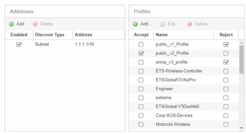
- Addresses
- Click the Add button in the Addresses list to allow you to add devices by seed address, subnet, or address range. Selecting Seed Address allows you to perform a discover for CDP, LLDP, SONMP, or EDP-compliant devices.
-
NOTE: The protocols for seed discovery are specified on the Administration tab. -
Click the Discover button at the bottom of the tab to begin the device discover. The results of the Discover process are displayed in the left-panel tree when added to the ExtremeCloud IQ Site Engine database.
- Profiles
- Select the access Profile(s) that give you the access you need (for example, Read, or Read/Write) to the devices you wish to discover by selecting the Accept checkbox. Select the Profiles that are not valid on the device being discovered by selecting the Reject checkbox. To create a profile, click the Add button or edit a profile by selecting the Edit button. If you discover an existing device using a different profile than the device is already using in the database, click Save to overwrite the profile currently being used in the database.
Actions
The Actions tab contains basic information about the device being discovered.
- Automatically Add Devices
- Selecting the Automatically Add Devices checkbox causes ExtremeCloud IQ Site Engine to automatically add devices to the database that match the address information you entered in the Discover section of the tab. If a device is discovered with more than one profile, the device is listed on the Network > Discovered tab, where you can decide which profile you want to add. When this box is NOT selected and a discover occurs, devices are added to the Network > Discovered tab, where they can be configured prior to being added to the database.
- Add Trap Receiver
- Select this checkbox to configure devices added to the site to send trap information to ExtremeCloud IQ Site Engine. You can define the trap configuration details on the Options > Trap tab. Depending on the device, ExtremeCloud IQ Site Engine creates the trap configuration via SNMP or a script.
- Add Syslog Receiver
- Select this checkbox to configure the devices added to the site to send syslog information to ExtremeCloud IQ Site Engine. You can define the syslog configuration details on the Options > Syslog tab. Depending on the device, ExtremeCloud IQ Site Engine creates the syslog configuration via SNMP or a script.
- Collection Mode
- Select None, Threshold Alarms, or Historical from the Collection Mode drop-down menu to indicate the mode used to collect device statistics on devices being discovered. ExtremeCloud IQ Site Engine uses the device and physical port statistics in reports.
- Collection Interval (minutes)
- Select the interval at which device and statistics (for devices being discovered) are collected. Extreme sets a minimum collection interval of five minutes and a maximum of 1440 minutes (24 hours).
- Add to Archive
- Select this checkbox to create an archive, which saves the configurations of the devices being discovered in the Network > Archives tab.
- Add to Map
- Select this checkbox to add the devices being discovered in the site to a map. To add a device to multiple maps, add it via this drop-down list and then manually add it via the Maps > Add to Map on the Devices tab.
- Custom Configuration
- Click the Add button to configure ExtremeCloud IQ Site Engine to automatically run a task (a script or workflow) when discovering a device in a particular device family that also matches the Topology you select.
-
CAUTION: If the script or workflow task selected for the Custom Configuration restarts the device, other actions selected to execute during discovery might not execute (for example, Add Trap Receiver). -
NOTE: Selecting a Topology of Any runs the task on all devices in a device family, regardless of the Topology configuration.
Policy
- Add Device to Policy Domain
- Select this checkbox to add the device to a policy domain you create on the Policy tab. When the checkbox is selected, use the Policy Domain drop-down list to select the policy domain to which the device is added. ExtremeCloud IQ Site Engine enforces are done automatically when a newly added device is discovered and added.
Click the Import VLANs button to import the VLAN definitions from the policy selected in the Policy Domain drop-down list.
Access Control
- Add Device to Access Control Engine Group
- Select this checkbox to add the device to an Access Control Engine Group you create on the Access Control tab. When the checkbox is selected, use the Access Control Engine Group drop-down list to select the engine group to which the device is added.
- If the device is an Access Control engine, ExtremeCloud IQ Site Engine adds it as an engine to the engine group.
- If the device is not an engine, ExtremeCloud IQ Site Engine adds it as a switch to up to two engines in the engine group. ExtremeCloud IQ Site Engine runs an enforce against the engine group if a switch is added.
Enable RADIUS Accounting - defines if the RADIUS Accounting is enabled or disabled. If Enable RADIUS Accounting is checked and the "Authentication Access Type" is " Manual RADIUS Configuration" then the Access Control Engine accepts RADIUS Accounting packets from that device. If Enable RADIUS Accounting is checked and "Authentication Access Type" is not "Manual RADIUS Configuration" then Access Control Engine enables RADIUS Accounting on the device and accepts RADIUS Accounting packets from that device.
Message-Authenticator Attribute - defines if the Access-Request must contain the Message-Authenticator attribute in the RADIUS communication with this device. Not every RADIUS client supports this attribute, but the security best practice is to require the Message-Authenticator attribute. If set to "Required", then RADIUS packets without the Message-Authenticator attribute are dropped.
Authentication Access Type - defines if the device is configured to use "Network Access" or "Management Access" or "Any Access" or the "Manual RADIUS Configuration".
Override RADIUS Attributes to Send - if checked then you can define what "RADIUS Attributes to Send" will be used. If unchecked then default "RADIUS Attributes to Send" will be used. The default is:
If the device is running the Fabric Engine operating system and the policy domain is specified, then Per-User ACLs RADIUS attributes are used.
If the device is running Fabric Engine operating system and the policy domain is not specified, the Fabric Attach RADIUS attributes are used.
If the device is running a policy capable operating system, for example, ExtremeXOS, then Extreme Policy RADIUS attributes are used.
- For more details, see Add Switches to ExtremeControl Engine Group.
- Enable Authentication Using Port Template
- Select this checkbox to allow users to authenticate to the device using a port template. Configure Port Templates in the Port Templates section of the tab.
ExtremeAnalytics
- Add as Flow/Telemetry Source to Home Engine using Management IP
- Select this checkbox to add application telemetry to the ExtremeAnalytics engine configured as the site's home engine. Flow Source is preferred if the device can be added as Flow Source and Telemetry Source.
- ERSPAN VLAN
- Enter the Encapsulated Remote Switch Port Analyzer (ERSPAN) VLAN to add to devices added to the site.
- Sample Rate
- Enter the rate of traffic ExtremeAnalytics samples to determine application information.
VRF/VLAN
The VRF/VLAN tab allows you to configure and manage virtual routing and forwarding (VRF), VLANs on the devices included in the site. Add a VRF or VLAN definition by selecting Add in the VRF Definition or VLAN Definition table, respectively. Edit an existing VRF or VLAN definition by selecting a VRF/VLAN and selecting Edit, or remove a VRF or VLAN definition by selecting a VRF/VLAN and selecting Delete.
| NOTE: | You must have a Fabric Manager license to configure VRFs. If you do not have one, this tab is just called VLAN. |
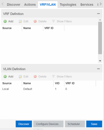
VRF Definition
- Source
- The Source represents the Site where the VRF settings were created. Local indicates the VRF was created in the selected site. When a VRF is created for a Site, any Sites created nested within that Site inherit the VRF settings from the Site. Changes or Deletions can only be made to the VRF in the site in which it was created (Source is Local).
- Name
- Displays the name of the VRF definition.
VLAN Definition
- Source
- The Source represents the Site where the VLAN settings were created. Local indicates the VLAN was created in the selected site. When a VLAN is created for a Site, any Sites created nested within that Site inherit the VLAN settings from the Site. Changes or Deletions can only be made to the VLAN in the site in which it was created (Source is Local).
- VID
- Indicates the VLAN ID for the VLAN. A unique number between 1 and 4094 that identifies a particular VLAN. VID 1 is reserved for the Default VLAN.
- Multicast
- Select to configure the service to distribute data to multiple recipients. Using multicast, a source can send a single copy of data to a single multicast address, which is then distributed to an entire group of recipients.
- IGMP Version
- Indicates which version of IGMP is utilized (Version 1 or Version 2).
- IGMP Querier
- Enter the address of the IGMP Querier. Use this feature when there is no multicast router in the VLAN to originate the queries.
- Virtual Routing
- Displays the version of VRRP the default gateway is using:
- NONE — Virtual routing is not configured on the VLAN.
- DvR - DvR (Direct Virtual Routing) is configured.
- VRRPv2 — VRRP version 2 is configured on the virtual router. VRRP version 2 only supports IP addresses in IPv4 format.
- VRRPv3 — VRRP version 3 is configured on the virtual router. VRRP version 3 supports IP addresses in both IPv4 and IPv6 formats.
- RSMLT — Routing Redundancy Method is configured on the VLAN. RSMLT requires that a Virtual IST is configured. If the device is not configured as a vIST pair, RSMLT can be selected, but the feature is not active. Once the vIST is configured, RSMLT becomes active.
NOTE: Virtual Routing is only supported on Fabric Engine devices.
- Virtual Routing Address
- The IP address for the virtual routing interface for either DvR or VRRP. The Virtual Routing address must be in the same subnet as the VLAN subnet address.
- VRRP ID
- An identifier devices use to determine peer devices that participate in a virtual routing interface.
- VRRP Priority
- A value used by VRRP peers to determine the role of each of the devices in the VLAN. The default value is 100. The device with the largest value is assigned the role of Controller. For example, in a VLAN with two routers, one with a VRRP Priority of 200 and one with a VRRP Priority of 100, the router with a VRRP Priority of 200 becomes the Controller. In the event of identical priority numbers, the devices use the MAC address to determine priority.
- VRRP Backup Master
- This option determines if the backup router is able to forward traffic independently outside of the VLAN (enabled), or must forward the traffic to the Controller router before it is forwarded outside of the VLAN (disabled).
- VRRP Advertisement Interval
- Indicates frequency (in seconds) that protocol packets are sent from the virtual router in the VLAN.
- VRRP Hold Down Timer
- Indicates the amount of time (in hundredths of a second) that the backup router waits for the primary router to respond before it becomes the primary router.
- DHCP Relay
- Indicates whether a Dynamic Host Configuration Protocol relay server is enabled for the VLAN. A DHCP relay receives and converts a DHCP broadcast message to dynamically assign an IP address to a device on the network.
- DHCP Snooping
- Indicates whether DHCP snooping is enabled for the VLAN. DHCP Snooping is a Layer 2 security feature, that provides network security by filtering untrusted DHCP messages received from the external network causing traffic attacks within the network. DHCP Snooping is based on the concept of trusted versus untrusted switch ports. Switch ports configured as trusted can forward DHCP Replies, and the untrusted switch ports cannot. DHCP Snooping acts like a firewall between untrusted hosts and DHCP servers.
- ARP Inspection
- Indicates whether ARP inspection is enabled. Dynamic ARP Inspection (DAI) is a security feature that validates ARP packets in the network. Without DAI, a malicious user can attack hosts, switches, and routers connected to the Layer 2 network by poisoning the ARP caches of systems connected to the subnet, and intercepting traffic intended for other hosts on the subnet. DAI prevents these attacks by intercepting, logging, and discarding the ARP packets with invalid IP to MAC address bindings. The switch dynamically builds the address binding table from the information gathered from the DHCP requests and replies when DHCP Snooping is enabled. The switch pairs the MAC address from the DHCP request with the IP address from the DHCP reply to create an entry in the DHCP binding table. When you enable DAI, the switch filters ARP packets on untrusted ports based on the source MAC and IP addresses seen on the switch port. The switch forwards an ARP packet when the source MAC and IP address matches an entry in the address binding table. Otherwise, the switch drops the ARP packet.
NOTE: DHCP Snooping must be enabled to use ARP Inspection.
DHCP Relay Servers
- Source
- Indicates the site from which the DHCP Relay Server is inherited. Currently, the VLAN definition Source can only be Local, indicating the DHCP Relay Server is configured in the current site.
Fabric Connect
The Fabric Connect tab allows you to select the topology definition. Use this tab to apply the fabric topology features you configure to a site.
- Topology Definition
- Select the Topology Definition that applies to the site. The Topology Definitions available in the drop-down list are configured in the Topology Definition tab.
- DvR Domain ID
- Select the DvR Domain ID that applies to the site. The DvR Domain IDs available in the drop-down list are configured in the Topology Definition tab.
Services
Select to configure the services configured in your virtual services network. Use this tab to select a service definition you create by configuring services on the Services tab to add to the site.
The Services tab displays all of the services included in a service application or all of the services included in a service definition, depending if you select a service application or a service definition in the left-panel, respectively. The Services tab is included in the Sites tab.
Services are created within service applications. You can include multiple services within an application. Service applications are then included within service definitions. You can also include multiple service applications within a service definition. A service definition that includes a complete set of services is then assigned to a site, which configures the fabric-enabled devices within that site.
Select the Service Definition assigned to the site from the Service Definition drop-down list. Select NONE if the services you configure are not assigned to a service definition.
| NOTE: | When services have been assigned to a site, they cannot be deleted; however, services not assigned to a service definition (where NONE has been selected) can be deleted from a site after they have been assigned to that site. |
L2 VSN
- UNI Type
- The User-Network-Interface (UNI) of the fabric service. The following interface types are available:
-
- Switched — A VLAN-ID and a port (VID, port) mapped to a Layer 2 VSN I-SID. With UNI type, VLAN-IDs can be reused on other ports and mapped to different ISIDs.
- Transparent - A physical port maps to a Layer 2 VSN I-SID (all traffic through the port, 802.1Q tagged or untagged, ingress and egress maps to the I-SID).
- CVLAN — a platform customer VLAN-ID.
NOTE: All VLANs on a Transparent Port UNI interface now share the same single MAC learning table of the Transparent Port UNI I-SID. - VLAN
- The customer VLAN-ID of the associated CVLAN UNI type.
- AutoSense Service Type
- Defines if the L2 VSN service is auto-assigned by the switch-level AutoSense detection. The following types are available:
-
- AP Untagged — If the AutoSense feature detects Access Point, then this service is automatically assigned to the port.
- Camera Untagged — If the AutoSense feature detects Camera then this service is automatically assigned to the port.
- Voice Untagged — If the AutoSense feature detects a VoIP device then this service is automatically assigned to the port.
- Voice Tagged — If the AutoSense feature detects a VoIP device then this service is automatically assigned to the port.
- Proxy Switch Auth Tagged — If the AutoSense feature detects a Fabric Attach switch capable of authenticating (ERS devices) then this service is automatically assigned to the port.
- Proxy Switch No Auth Untagged — If the AutoSense feature detects a Fabric Attach switch is not capable of authenticating (Switch Engine devices) then this service is automatically assigned to the port.
- Proxy Switch Auth & Proxy Switch No Auth — If the AutoSense feature detects any physical Fabric Attach switch (ERS/EXOS/Switch Engine device) then this service is automatically assigned to the port.
- Data Untagged — If the AutoSense feature does not detect a device type then this service is automatically assigned to the port.
- None — AutoSense is not related to this L2VSN service.
| NOTE: | Each AutoSense Service Type can only be used once on a switch. The switch cannot use two different service IDs with the same AutoSense Service Type. |
- AutoSense Service CVID
- The AutoSense Service CVID value defines the 802.1q VLAN tag sent from the switch to the device. If the AutoSense Service Type is Voice Tagged or Proxy Switch Auth Tagged or Proxy Switch Auth & Proxy Switch No Auth then AutoSense Service CVID must be defined. The value range is 1-4094.
- Port Template
- If the UNI Type is Switched or Transparent you can select from the Global Port templates to define the purpose of the port.
L3 VSN
- Direct Route
- Select to indicate the service sends IP packets directly to another device without going through a third device.
LAG Topologies
The LAG Topologies tab allows you to configure link aggregation group topologies you include on devices in the site.
- Topology Definition
- Select the Topology Definition for the LAG in the drop-down list.
- Device 1 VLAN IP Address/Mask
- Enter IP address and mask for the first device or cluster included in the LAG.
- Device 2 VLAN IP Address/Mask
- Enter IP address and mask for the second device or cluster included in the LAG.
- LACP MAC
- Enter the MAC address for the device located between two devices designed to detect when a link is down, if you use link aggregation control protocol (LACP).
- vIST
- Select the Virtual IST (vIST) type. vIST provides the ability to dual-home hosts, servers and other network devices to a pair of Multi-Chassis Link Aggregation (MLAG) enabled devices.
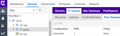
Port Templates
The Port Templates tab has two panels. The top panel displays information about user-defined port templates. For more information, see Port Templates Panel.
The bottom panel displays information about automated port templates. For more information, see ZTP+ Automated Templates Panel.
Port Templates Panel
The Port Templates panel displays port information for those devices discovered in a site. The port templates you configure in this table are available for the devices included in this site in the Configure Device window.
Click the Add (![]() ) button to add a port template to the table.
) button to add a port template to the table.
Select a port template and select the Edit ( ) button to make changes to the selected port template.
Select a user-created port template and select the Delete ( ) button to delete it from the table. You can not delete system-defined port templates.
Select the Local Only button as a toggle button to display local templates only and, alternately, to display all templates.
Click Save to save your additions or changes.
The following columns are included on the Ports Templates panel:
- Source
- Indicates the site which defines the values used for the Port Template.
- Port templates with a Source of Global can only be edited in the /World site.
- A Source of Local indicates that the values are coming from the currently selected site. In order to change the value of a Port Template, select the Port Templates tab for the site that shows the Source as Local. When creating a new site, the values of the new site's Port Templates are inherited from the parent site.
When you create port template after creating a new site, the new port template is also created in the /World site. All port templates in the /World site display a Local for Source. You can modify the values of the port template in both the /World site and in the site where the port template was created. Sites that are the children of the /World site display the Source for the port template values as /World. Sites that are the children of the site in which the port template was created display the Source for the port template values as the site where the port template was created.
When the Source is not Local, the port template values act like default values for the site. Editing the port template in the site and changing the Source to Local allows you to edit the port template for the current site and the sites that are children of that site.
- Configuration
- Indicates the purpose of a port. Defines the behavior of ports on devices in a site, based on the role of that port. After you configure your port templates in this table, select the Configuration for devices in the site in the Configure Device window. The configuration of the port is initially discovered by ExtremeCloud IQ Site Engine during discovery or during a ZTP+ process, but can be changed to meet the needs of the devices in your site. The following port types are included:
- Access
- Applies access port template settings to the device in the site.
- Interswitch
- Applies interswitch port template settings to the device in the site.
- Management
- Applies management port template settings to the device in the site.
- AP
- Applies AP port template settings to the device in the site.
- Phone
- Applies phone port template settings to the device in the site.
- Router
- Applies router port template settings to the device in the site.
- Printer
- Applies printer port template settings to the device in the site.
- Security
- Applies security port template settings to the device in the site.
- IoT
- Applies guest or external device port template settings to the device in the site.
- vSwitch
- Applies virtual switch port template settings to the device in the site.
- Other
- PVID
- The port's VLAN ID.
-
The PVID value "None [0]" means incoming untagged traffic is not assigned to any VLAN. The value "None [0]" is compatible with Switch Engine persona devices.
- Default Role
- The policy role assigned to the selected port. To assign policy to the selected port, select Add Device to Policy Domain and select a Policy Domain from the drop-down list in the Actions tab. ExtremeCloud IQ Site Engine assigns policy to the port after a successful policy domain enforce.
- Authentication
- Use the drop-down list to determine whether authentication is configured to the port:
- None — No authentication is required to access the port.
- 802.1X — Select this option to enable 802.1X authentication to the port.
- MAC Auth — Select this option to enable authentication based on the users MAC address.
WARNING: Configuring the authentication could affect communication to a device and result in loss of connectivity through the interswitch link ports if not detected or configured properly during the discovery process. If you are configuring the policy and authentication on the interswitch link, it's strongly recommended to ensure neighbor discovery protocols such as LLDP, EDP, and CDP are enabled before enabling the authentication using port templates.
- VLAN Trunk
- Automatically configures a port as a VLAN trunk when you check one box in the VLAN Trunk column. For more information, see Fabric Assist.
- Tagged
- Indicates the port's egress state is tagged. If you check the VLAN Trunk column, Fabric Assist automatically configures all the VLANs on the port as tagged. For more information, see Fabric Assist.
- Fabric Enable
- Indicates the fabric functionality is enabled on the port.
-
NOTE: Fabric Enable options are only configurable for Global port templates. You can create a global port template on the World site level. -
ExtremeCloud IQ Site Engine can extend FA functionality to ExtremeXOS/Switch Engine devices and provision them as FA Proxy devices. Select Fabric Attach or Fabric Attach and Switched UNI or Auto Sense from the drop-down list to enable the port on a Fabric Engine device (acting as FA Server) to connect to an ExtremeXOS/Switch Engine device (acting as FA Proxy).- Fabric Attach - Enable Fabric Attach server functionality on the port of a Fabric Engine device acting as a Fabric Attach server) to connect to an ExtremeXOS/Switch Engine device (acting as a Fabric Attach proxy).
- Fabric Attach and Switched UNI - Enable Fabric Attach server functionality on the port of a Fabric Engine device acting as a Fabric Attach server) to connect to an ExtremeXOS/Switch Engine device (acting as a Fabric Attach proxy). When selecting this option, the port is configured for both features, but only one feature is active at any one time.
- Auto Sense - Select Auto Sense on the port of a Fabric Engine device to enable the port to automatically sense and configure automatically sense and configure the appropriate Fabric settings for the port. These settings include the following:
- PVID
- VLAN Trunk
- Tagged
- Untagged
- Fabric Mode
- Fabric Auth Type
- Fabric Auth Key
- Fabric Connect Drop STP-BPDU
- BPDU Guard
- Authentication
NOTE: If Fabric Enable is Auto Sense the Fabric settings listed above are not configurable.
- Node Alias
- Select to enable the node alias function on the port. The node alias settings are automatically enabled if Access Control is enabled on the device.
- Span Guard
- Select to enable Span Guard, which allows the device to shut down a network port if it receives a BPDU (bridge protocol data unit). Enable this feature on network edge ports to prevent rogue STA-aware devices from disrupting the existing Spanning Tree.
- Loop Protect
- Select to prevent loop formation in a network with redundant paths by requiring ports to receive type 2 BPDUs (RSTP/MSTP) on point‐to‐point interswitch links.
- If the ports receive the BPDUs, the link's State becomes Forwarding.
- If a BPDU timeout occurs on the ports, its State becomes Listening until a BPDU is received.
- MVRP
- Indicates that the Multiple VLAN Registration Protocol (MVRP) is enabled for the port. If MVRP has been enabled globally, interswitch ports are automatically enabled and access ports default to disabled.
- SLPP
- Indicates Simple Loop Prevention Protocol (SLPP) is enabled on the port. SLPP provides active protection against Layer 2 network loops on a per-VLAN basis. If an SLPP packet is received, the port is disabled for the amount of time configured in the SLPP Timer field.
NOTE: If SLPP is enabled, SLPP Guard is not available.
- SLPP Guard
- Indicates whether SLPP Guard is enabled on the port. Use SLPP Guard to provide additional loop protection to protect wiring closets from erroneous connections. SLPP Guard requires SLPP to be enabled. SLPP detects loops in an SMLT network. Because SMLT networks disable Spanning Tree (STP), Rapid Spanning Tree (RSTP), or Multiple Spanning Tree Protocol (MSTP) for participating ports, SLPP Guard provides additional network loop protection, extending the loop detection to individual edge access ports. SLPP Guard can be configured on MLT or LAG ports. If the edge switch with SLPP Guard enabled receives an SLPP-PDU packet on a port, SLPP Guard operationally disables the port for the configured timeout interval in the SLPP Guard Timer field and appropriate log messages and SNMP traps are generated. If the disabled port does not receive any SLPP-PDU packets after the configured timeout interval expires, the port automatically reenables and generates a local log message, a syslog message, and SNMP traps, if configured.
NOTE: If SLPP Guard is enabled, SLPP is not available
- SLPP Guard Timer
- Indicates the amount of time after receiving an SLPP packet before the port is reenabled.
- DHCP Snooping
- Specifies the trust factor of the port for DHCP Snooping. The agent at the switch determines if DHCP reply packets are forwarded based on the DHCP Snooping mode of the VLAN and the trusted state of the port. If the value is "Trusted", the agent trusts the device on the port. If the value is "Untrusted", the agent does not trust the device on the port.
- ARP Inspection
- Dynamic ARP Inspection (DAI) is a security feature that validates ARP packets in the network. Without DAI, a malicious user can attack hosts, switches, and routers connected to the Layer 2 network by poisoning the ARP caches of systems connected to the subnet and intercepting traffic intended for other hosts on the subnet. DAI can prevent attacks by intercepting, logging, and discarding the ARP packets with invalid IP to MAC address bindings. The switch dynamically builds the address binding table from the information gathered from the DHCP requests and replies when DHCP Snooping is enabled. The switch pairs the MAC address from the DHCP request with the IP address from the DHCP reply to create an entry in the DHCP binding table. Values are "Trusted" and "Untrusted".
- Source Guard
- IP Source Guard (IPSG) is a Layer 2 port-to-port feature that works closely with DHCP Snooping. IPSG can prevent IP spoofing by allowing only IP addresses obtained using DHCP Snooping. When you enable IPSG on an untrusted port with DHCP Snooping enabled, an IP filter is automatically created or deleted for that port based on the information stored in the corresponding DHCP Snooping binding table entry. When a connecting client receives a valid IP address from the DHCP server, the filter installed on the port allows traffic only from that assigned IP address. If the value is "Disabled" the Source Guard is disabled. If the value is "IP" the IP Source Guard feature is enabled.
- Collection Interval (minutes)
- Indicates the interval (in minutes) at which port statistics are collected.
ZTP+ Automated Templates
The ZTP+ Automated Templates displays information about templates configured by family. These templates are listed in priority order, which means they are evaluated in the order they are displayed. You can change the order by using the priority arrows in the toolbar or dragging and dropping a template.
| NOTE: | ExtremeCloud IQ Site Engine supports automated port templates for ZTP+ devices only. |
The automated port templates panel has two sections: Device Mappings on the left and Port Mappings on the right.
On the left side, specify the name for the Device Mapping and then select the family and devices you want to apply the template to. Optionally, you can also match based on an IP range.
The right side displays the port mappings associated with the device mapping that you selected on the left side. The bindings are in priority order, and the template matches the ports in the order they are listed. You can change the order by using the priority arrows in the toolbar or dragging and dropping a template.

Click Add (![]() ) to add a device mapping to the table.
) to add a device mapping to the table.
Select a device mapping and select Edit () to make changes.
Select a device mapping and select Delete () to delete it from the table.
Click Save to save your changes.
The following columns are included on the Device Mappings panel:
- Priority
- Displays the order in which device mappings are evaluated.
- Name
- The name of the device mapping.
- Enabled
- Indicates whether the device mapping is enabled or disabled.
- Family
- Specifies the family of devices to which the device mapping applies.
- Devices
- Specifies which device within the family to which the template applies.
- IP Range
- Specifies a single IP address or a range of addresses in the following formats:
-
- 1.2.3.4 (v4)
- 1111:2222::3333:4444 (v6)
- 1.2.3.4/24 (v4 with mask)
- ::1/64 (v6 with mask)
- 1.2.3.4-2.3.4.5 (range)
- 1::1-1::2 (range)
The following columns are included in the Port Templates panel:
- Priority
- Displays the order in which port templates are evaluated.
- Template
- Displays the list of available automated port templates.
- Port Binding accepts any of the following formats (device dependent):
-
- 1 (single port)
- 1-5 (port range)
- 1,3,5 (comma separated ports)
- 1-3,5-7 (comma separated port ranges)
- * (wildcard)
- Ports
- Displays the list of configured ports next to their associated template.
For devices that require slot and port numbers, use the appropriate format for the device:
- Single Port:
- 210-Series: "1/1" or "1/1, 1/3, 1/5, 1/7"
- 220-Series: "1/0/1" or "1/0/1, 1/0/3, 1/0/5, 1/0/7"
- ERS: "1/1" or "1/1, 1/3, 1/5, 1/7"
- ExtremeXOS/Switch Engine: "1:1" or "1:1,1:3,1:5,1:7"
- ExtremeXOS/Switch Engine Stack/VPEX: "1:1" or "1:1, 1:3, 1:5, 1:7"
- SLX: "Ethernet 0/1" or "Ethernet 0/1, Ethernet 0/3"
- Port Ranges:
- 210-Series: "1/5-1/7" or "100/5-100/7, 111/9-111/12, 113/15-113/19"
- 220-Series: "1/0/1-1/0/5" or "1/0/1, 1/0/3, 1/0/5, 1/0/7"
- ERS: "1/5 - 1/7" or "100/5-100/7, 111/9-111/12, 113/15-113/19"
- ExtremeXOS/Switch Engine: "1:5-1:7" or "1:5-1:7, 1:9-1:12, 1:15-1:19"
- ExtremeXOS/Switch Engine Stack: "1:5-1:7" or "1:5-1:7, 2:9-2:12, 3:15-3:19"
- ExtremeXOS/Switch Engine channelized ports are included in the master port: "1:24" is equal to "1:24:1,1:24:2,1:24:3,1:24:4"
- SLX: "Ethernet 0/1-Ethernet 0/4" or "Ethernet 0/1-Ethernet 0/5, Ethernet 0/8-Ethernet 0/15"
- Wildcarding:
- "*" is always allowed, matches anything, useful as default rule at the end of a set of bindings
- In a single port scenario, the wildcard may be applied as the slot or port value:
- 210-Series: "*/1" or "1/*"
- 220-Series: "*/0/1" or "1/0/*"
- ERS: "*/1" or "1/*"
- ExtremeXOS/Switch Engine: "*"
- ExtremeXOS/Switch Engine Stack/VPEX: "*:1" or "1:*"
- SLX: "Ethernet 0/*" or "Ethernet */3,Ethernet */5"
- Port ranges support limited use of wildcards: for port ranges in the slot/port or slot/unit/port format, use the wildcard on the same item.
To refresh the port templates, go the Devices view and select one or more port templates. Then, right-click More Actions > Refresh ZTP+ Automated Templates. This updates the port template settings on all selected devices based on the configured automated port templates. This action also creates an operation in the Operations view and generates an event detailing the results.
After configuring the automated port templates, when ExtremeCloud IQ Site Engine discovers devices via ZTP+ and asks for configuration, the automated port templates are automatically assigned to the ports on the device.
ZTP+ Device Defaults
The ZTP+ Device Defaults tab contains information about a device with ZTP+ (Zero Touch Provisioning Plus) enabled. Use the following dialog to specify the parameters that should be used during the process of learning about a ZTP+ device. ExtremeCloud IQ Site Engine then applies these configuration templates to devices that you add to a site in your network.
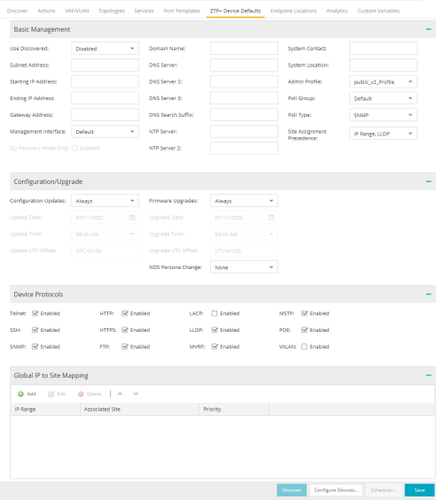
Basic Management
- Use Discovered
- Use the drop-down list to select if ExtremeCloud IQ Site Engine assigns the IP address, IP address and Management Interface, or Management Interface to the ZTP+ device when it is discovered:
- IP — ExtremeCloud IQ Site Engine uses the Discovered IP assigned when the device was discovered. Select the Management Interface (the VLAN interface used to manage the device) manually.
- IP and Management Interface — ExtremeCloud IQ Site Engine uses the Discovered IP and the Management Interface that were assigned when the device was discovered.
- Management Interface — ExtremeCloud IQ Site Engine uses the Management Interface that was defined when the device was discovered. Enter the IP address and subnet, Gateway Address, Domain Name, and DNS Server in the tab (along with any of the optional fields) and then save.
- Disabled — Configure the IP address and subnet, Gateway Address, Domain Name and DNS Server in the tab (along with any of the optional fields) and then save.
- Starting IP Address
- The Starting IP Address field allows you to set the starting IP address of the IP address range for the ZTP+ devices associated with the site.
- Ending IP Address
- The Ending IP Address field allows you to set the ending IP address of the IP address range for the ZTP+ devices associated with the site.
- Management Interface
- Select the interface that the device uses for Management and assign the device IP to that interface.
- CLI Recovery Mode Only
- Select the checkbox to disable the CLI account while the device is able to communicate with ExtremeCloud IQ Site Engine.
If connectivity between the device and ExtremeCloud IQ Site Engine is lost, the device enables the CLI account defined in the profile so the user can gain local access.
When connectivity between the device and ExtremeCloud IQ Site Engine is re-established, the CLI account is disabled again.
NOTE: Only devices managed using ZTP+ support this functionality.
- Domain Name
- Enter a value in the Domain Name field to configure the domain name on the ZTP+ devices associated with the site.
- DNS Server
- The DNS Server field allows you to set the DNS server address on the ZTP+ devices associated with the site.
- DNS Server 2
- The DNS Server 2 field allows you to set the secondary DNS server address on the ZTP+ devices associated with the site.
- DNS Server 3
- The DNS Server 3 field allows you to set the tertiary DNS server address on the ZTP+ devices associated with the site.
- DNS Search Suffix
- The DNS Search Suffix field allows you add additional comma-separated entries to DNS search suffix list configured on the device. Support for the DNS search suffix is dependent on the device operating system and version. Refer to your device specifications to determine the maximum number of entries that you can add.
- NTP Server
- The NTP Server field allows you to set the NTP server address on the ZTP+ devices being discovered.
- NTP Server 2
- The NTP Server 2 field allows you to set the secondary NTP server address on the ZTP+ devices associated with the site.
- System Contact
- Allows you to specify contact information for the person maintaining the device. Additionally, enter a backslash "\" between contacts to create a device group in a tiered tree structure. For example, to move the device into a device group called "John's Devices" within a device group called "Quality Assurance Testing", enter Quality Assurance Testing\John's Devices in this field.
- Admin Profile
- Use the drop-down list to select the access Profile that gives ExtremeCloud IQ Site Engine administrative access to the ZTP+ devices associated with the site. Use the Profiles list in the Discover section of the Site tab to create or edit a profile. If you discover an existing device using a different profile than the device is already using in the database, click Save to overwrite the device profile currently being used in the database.
- Poll Group
- Use the drop-down list to select a Poll Group for the discovered ZTP+ devices. ExtremeCloud IQ Site Engine provides three distinct poll groups (defined in the Status Polling options (Administration > Options) that each specify a unique poll frequency. When you save newly discovered devices to the database, they are polled with the poll group specified here. If you save discovered devices that already exist in the database, the poll group specified here overwrites the poll group currently being used in the database.
NOTE: If you select Not Polled, the Poll Group is only used if/when the Poll Type is changed to SNMP or Ping.
- Poll Type
- Use the drop-down list to select the Poll Type for devices included in the site:
- Select Not Polled if you do not want to poll the devices.
- Select Ping for the Poll Type if the Profile for the IP Range is also set to Ping.
- Select SNMP to poll the device using SNMP. The SNMP version (SNMPv1 or SNMPv3) is determined by the Profile specified for the IP Range.
- Select Maintenance if you do not want to poll the devices temporarily. Using this Poll Type allows you to search for devices set to Maintenance to change them back to their regular Poll Type when maintenance on the device is complete.
- Select ZTP+ for devices managed by ZTP+ and created through the ZTP+ process. When the Poll Type is ZTP+ the ExtremeCloud IQ Site Engine does not initiate a poll, instead the ExtremeCloud IQ Site Engine receives a message from the device to determine the status. The ZTP+ Poll Type is incompatible with Switch Engine devices running with FIPS mode enabled.
For example, if ExtremeCloud IQ Site Engine does not receive a message from a device or Fabric Manager for three times the amount of time defined in the Poll Interval for the Poll Group of the device, then the Status is Contact Lost. When ExtremeCloud IQ Site Engine receives a message from the device, the Device Status is Contact Established.
- Site Assignment Precedence
- Set the precedence by which ZTP+ devices will be assigned to the site. This field is used in conjunction with the Global IP to Site Mapping settings in determining the site assignment. For example, during the device configuration, if the precedence is set to IP range only, the device will try to match any of the single IP addresses or fit within a range. If an IP does not match any value in the table then it will default to /World.
- The following values can be set:
- IP Range, LLDP: Uses IP range first. If no IP range is set, uses LLDP instead.
- LLDP, IP Range: Uses LLDP first. If LLDP is not available, uses IP range instead.
- LLDP Only: Uses LLDP only.
- IP Range Only: Uses IP range only.
- None: Uses neither LLDP or IP range.
- All discovered ZTP+ devices are assigned to the site based on the this value. However, you can manually change the value for individual devices in the device configuration.
- If there are multiple IP ranges that match the site, the device will use the mapping that has the highest priority.
Configuration/Upgrade
- Configuration Updates
- Select the frequency for which ExtremeCloud IQ Site Engine checks for configuration updates for devices with a Poll Type as ZTP+ associated with the site.
- NOS Persona Change
-
Select To Fabric Engine to change the Network Operating System (NOS) of a universal switch currently running Switch Engine to Fabric Engine. The NOS Persona Change field has values of None and To Fabric Engine. The persona change to Fabric Engine requires a Fabric Engine firmware in Set as Reference image,
When the switch completes the persona change from Switch Engine to Fabric Engine, all previous Switch Engine references for the switch are removed from ExtremeCloud IQ Site Engine. Including but not limited to the Discovered panel, and the Device Tree. You must now stage configuration for the 'new' Fabric Engine switch in ExtremeCloud IQ Site Engine.
-
IMPORTANT: The NOS persona change To Fabric Engine is ignored if:
-
The universal switch is running EXOS (Upgrade to Switch Engine before changing persona)
-
The non-universal switch is running EXOS (A firmware upgrade for EXOS occurs if the EXOS image is set as reference image)
-
You did not specify a Fabric Engine reference image (The destination firmware must be a Fabric Engine firmware set as reference image)
A Switch Engine reference image is not required. If you only specify a Fabric Engine firmware in Set as Reference Image, then only one firmware upgrade occurs on the switch during the change from Switch Engine to Fabric Engine, which increases the persona change speed.
Upload the Fabric Engine firmware to both of the TFTP and SFTP directories (Network > Firmware > Upload...). You must specify the Fabric Engine firmware located in the SFTP directory as a reference image.
-
-
NOTE: You can specify one reference image for upgrading EXOS to Switch Engine, and another reference image for a persona change from Switch Engine to Fabric Engine.
If you specify reference images for Switch Engine and for Fabric Engine and the universal switch is not currently running the Switch Engine reference image, a firmware upgrade for Switch Engine occurs before the persona change to Fabric Engine.
- Update Date
- Select the date on which ExtremeCloud IQ Site Engine updates the configuration for your devices with a Poll Type as ZTP+ associated with the site when you select Scheduled for Configuration Updates.
- Update Time
- Select the time at which ExtremeCloud IQ Site Engine updates the configuration for your devices with a Poll Type as ZTP+ associated with the site when you select Scheduled for Configuration Updates.
- Update UTC Offset
- Select your time zone based on the number of hours you are offset from the Universal Time Coordinated.
- Firmware Upgrades
- Select the frequency for which ExtremeCloud IQ Site Engine checks for firmware upgrades for your devices with a Poll Type as ZTP+ associated with the site.
- Upgrade Date
- Select the date on which ExtremeCloud IQ Site Engine upgrades the firmware for your devices with a Poll Type as ZTP+ associated with the site when you select Scheduled for Firmware Upgrades.
- Upgrade Time
- Select the time at which ExtremeCloud IQ Site Engine upgrades the firmware for your devices with a Poll Type as ZTP+ associated with the site when you select Scheduled for Firmware Upgrades.
- Upgrade UTC Offset
- Select your time zone based on the number of hours you are offset from the Universal Time Coordinated.
Device Protocols/Features
- HTTPS
- Select the checkbox to enable HTTPS (Hypertext Transfer Protocol Secure) access on the ZTP+ device.
NOTE: To enable HTTPS access, an SSL certificate must be configured on the device.
- SNMP
- Select the checkbox to enable SNMP (Simple Network Management Protocol) access on the ZTP+ device.
- LACP
- Select the checkbox to enable LACP (Link Aggregation Control Protocol) access on the ZTP+ device.
- MSTP
- Select the checkbox to enable MSTP (Multiple Spanning Tree Protocol) access on the ZTP+ device.
- MVRP
- Select the checkbox to enable MVRP (Multiple VLAN Registration Protocol) access on the ZTP+ device.
- POE
- Select the checkbox to indicate the ZTP+ devices being discovered for the site are electrically powered by Ethernet cable.
- VXLAN
- Select the checkbox to indicate the ZTP+ devices being discovered for this site use VXLAN to tunnel Layer 2 traffic over a Layer 3 network.
NOTE: ZTP+ does not currently provision a Layer 3 network with which VXLAN operates. If your ZTP+ devices use VXLAN, the Layer 3 underlay network must be manually provisioned.
- DvR Leaf
- Select the checkbox to indicate the ZTP+ devices being discovered for the site operate in DvR Leaf mode. The DvR Leaf flag is enabled. Only devices running Fabric Engine support the DvR Leaf feature.
Global IP To Site Mapping
- Associated Site
- Select a site from the drop-down list that the discovered ZTP+ devices will be associated with when the devices are discovered.
Endpoint Locations
Use the Endpoint Locations tab to define the geographical location of the site and addresses in it. After the geographical locations are defined for your devices, flows on the Application Flows tab display geographical information depending on the device on which the flow is observed.
Select the Add Address button at the top of the table to add an additional address to the table. Select the Edit button to modify the site or selected address of the site. The Move button allows you to move an address to a different site in the drop-down list. Select the Remove button to delete a selected address from the table. These options are also accessible when you right-click an address in the table.
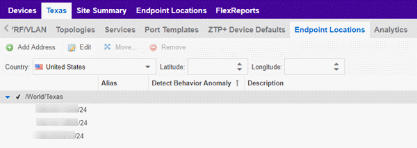
Use the Country, Latitude, and Longitude drop-down lists to configure or change the following information for the site:
The following columns are displayed in the Endpoint Locations table:
- Tracked
- This column displays the name of the site or the IP Address/Mask of the devices on the site. A check mark to the left of the site name indicates it is a Tracked Site. Right-click any site to either add or remove the site from your Tracked Sites list.
Analytics
The Analytics tab allows you to configure the default ExtremeAnalytics functionality for the devices in the site.
- Analytics Role
- Allows you to indicate the purpose of the devices added to the site: Access, Core, Data Center, DMZ. This field is informational only.
- Analytics Home Engine
- Displays the ExtremeAnalytics engine located with the devices associated with the site.
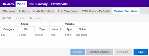
Custom Variables
The Custom Variables tab allows you to add, edit, or delete variables used in ExtremeCloud IQ Site Engine.
Variables you create serve as a placeholder for a specific value. The fields included in the Scope section determine where the variable is used in ExtremeCloud IQ Site Engine, while the fields in the Variable section allow you to define a value for the variable. After you create a variable, ExtremeCloud IQ Site Engine automatically substitutes the Value you define in the appropriate feature of ExtremeCloud IQ Site Engine when the criteria specified in the Scope section is met. Variables you create on the Site tab can then be used in a configuration template, script or workflow, in a CLI command, or in a third-party application via the Northbound Interface.
| NOTE: | Custom variables you create are not displayed in ExtremeCloud IQ Site Engine. To view and reference the variables, use the Northbound Interface functionality in the Diagnostics tab. |
 .
.
Scope
- Category
- Displays where the variable is used in ExtremeCloud IQ Site Engine. Select Port Template, Site, or Topology from the drop-down list, depending on the purpose of the variable.
- Site
- Defines the site in which the variable is used.
- Global indicates ExtremeCloud IQ Site Engine uses the variable for all sites.
- Selecting /World indicates ExtremeCloud IQ Site Engine uses the variable for all devices added to the /World site. Devices added to a site other than /World do not use the variable.
- Selecting the current site also creates an additional variable with a Site of Global. This allows you to use the variable in workflows run on devices not included in the current site.
- Type
- Defines the type of Port Template or Topology for which the variable applies.
The values in this drop-down list change depending on what Category you select.
- Port Template — Indicates the Port Configuration for which the variable is used by ExtremeCloud IQ Site Engine.
- Topology — Displays the type of network topology for which the variable is used by ExtremeCloud IQ Site Engine.
Variable
- Type
- Defines the type of information the variable is substituting. Select Boolean, IP, MAC Address, Number, String, or Subnet from the drop-down list.
- Value
- Displays the value ExtremeCloud IQ Site Engine uses when substituting the variable. Enter a value associated with the variable type you define. For example, if the variable type is Boolean, choose True or False; if the attribute type is IP, enter the IP Address of the variable).
- Add
- Click the button to add a row to the table where you can create a new custom variable.
- Cancel
- Click the Cancel button to cancel the new variable or the changes you made to an existing variable.
XIQ Location
Devices assigned to the site are automatically mapped to the specified locations in ExtremeCloud IQ, and the XIQ location is assigned on the site level. Values in the drop down are obtained from ExtremeCloud IQ. The assignment of the device to the XIQ location is configurable in the ExtremeCloud IQ Site Engine, but not in ExtremeCloud IQ.
| NOTE: |
The XIQ Location tab is only displayed in connected deployment mode. |
Buttons
- Edit Devices
- Clicking Configure Devices opens the Configure Device window for all of the devices added to the site. This allows you to change the configuration of a single device or a subset of devices within the site.
- Save
- Clicking Save saves any changes you make to a site. This button displays after making a change to the tab.
- Cancel
- Clicking Cancel discards any changes you make to a site. This button displays after making a change to the tab.
- Discover
- Clicking Discover adds to the site any new devices that match the criteria entered in the Discover section of the window. This button displays after selecting Create or Save.
- Scheduler
- Clicking Scheduler opens the Add Scheduled Task window, where you can create a new task that automatically adds devices matching the criteria entered in the Discover section of the Site tab to the site. This button displays after selecting Create or Save.
NOTE: After you create a scheduled task to discover devices, edit or delete the task on the Scheduled Tasks tab.
For information on related help topics:
For information on related topics: