ExtremeCloud IQ Site Engine includes tools that you can use to create geographic and topology maps of devices and floor plans of wireless access points (APs) on your network. Use maps to view devices and network connections, device and alarm status; access device and connection information via a right-click menu off the device; and search for devices, APs, and wired or wireless clients.
You can include port extenders in a map. If you choose not to add port extenders to a map, the ports on the port extender are shown as part of the controlling bridge.
Maps are configured in various places on the Network > Devices tab.
You can create three types of maps, each presenting a different visual representation of your network:
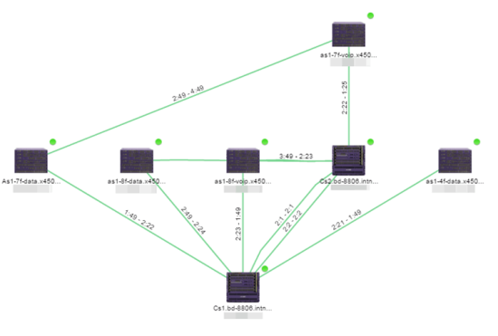
- Topology (default) — A topology map shows how devices are connected in a network, specifically, the state and speed of the network connections between devices as well as the state of the devices in the network. You can also create a topology map with a background image, giving you additional information about the devices and connections that make up the network.
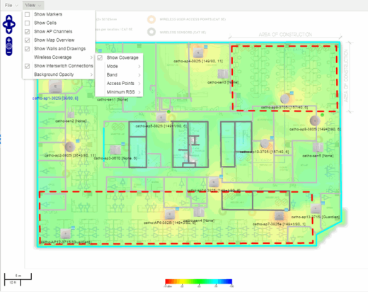
For additional information about devices and links in a Topology map, see the Viewing Alarm and Device Status and Link Information sections. - Floorplan — The floorplan map displays the location of APs in a floorplan you configure. Using information about the size and composition of the building, this map provides an overview of the coverage of wireless APs.
- Geographic — The Geographic map shows a global or regional view where network locations are shown geographically. This map is useful for networks spread across large geographical areas or as a top-level map used to organize multiple networks in different locations.
NOTE: The geographic map type is hosted by OpenStreetMap on an external server. For users with security concerns or if access to third-party servers is prohibited, use the topology map type. 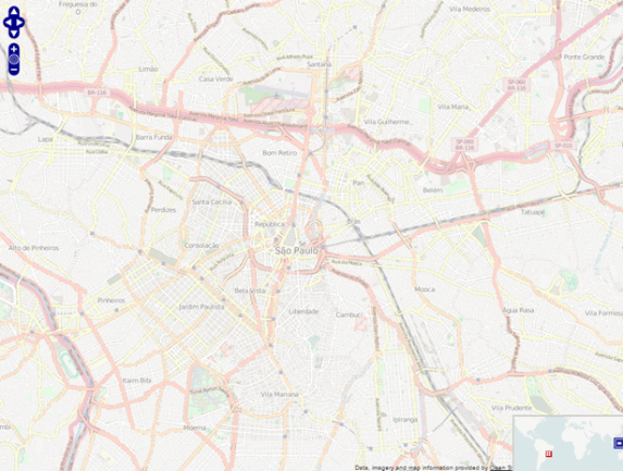
| NOTE: | For additional information, see Advanced Map Features. |
This Help topic provides the following information for Maps.
For information on creating maps, see How to Create and Edit Maps.
For information on advanced location (triangulation) and wireless coverage maps, see Advanced Map Features.
To view or search Maps, you must be a member of an authorization group assigned the OneView > Maps > Maps Read Access or Maps Read/Write Access capability.
After you create a map, you can then make it a site. Sites allow you to set a default configuration for devices added to your network.
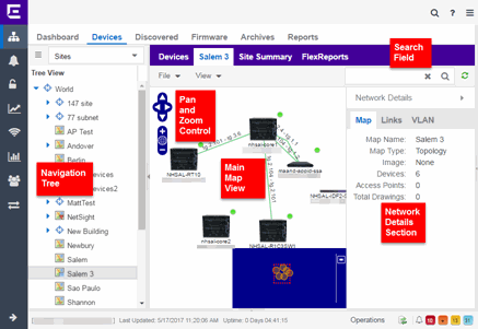
Navigating the Map Tab
World Map Navigation Tree
As you create your maps, they appear in the Network > Devices tab navigation tree by selecting Sites, nested under the map you configure as the Parent Map.
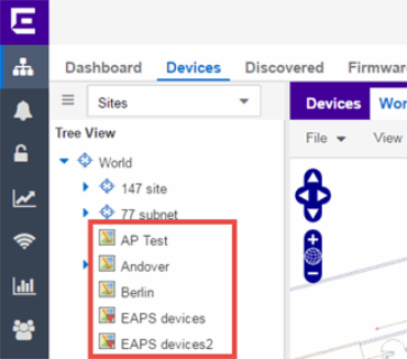
As shown in the image above, you also have the ability to nest maps within other maps. This allows you to organize certain maps as a subset of other maps (for example, creating a building map and then creating a map for each of the floors of the building).
Create Map
Right-click a map in the right-panel navigation tree and select Maps > Create New Map to create a new map. The first map you create is nested under the World Map. All subsequent maps are nested under the map you right-click when creating the new map.
Edit Map
Right-click a map in the navigation tree and select Maps > Edit Map to open an existing map in edit mode. Edit mode allows you to add new or move existing devices, APs, and map links on a map.
Import Map
You can also import a saved map by right-clicking a map in the navigation tree and selecting Maps > Import Map. This opens the Import Map window.
Main Map View
The Main Map view displays your map with all of the devices, network connections, links, or APs, depending on the type of map. In the Main Map view, you can reorganize the orientation of elements in your map and view the status and details of the elements within the map. The Main Map view also contains the following controls for working with maps:
File, View, and Tool Menus
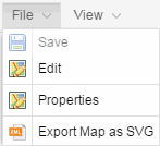
File Menu
The File menu allows you to change the map information, the devices, APs, and links displayed on the map, and export the map from ExtremeCloud IQ Site Engine.
| NOTE: |
To change the image used for a device type in a map, right-click the device and select Customize Device Type Image. The Upload Custom Device Type Image window appears where you can drag and drop the new image file. The height and width of image files must be less than 1,000 pixels. |
Selecting Properties opens the Map Properties window, which allows you to view and edit information about the map, including the map type, name, and background image. The Export Map as SVG and Export Map as ZIP options are available in the File menu, which allow you to export the map in SVG or ZIP format, respectively.
When exporting a map in SVG format, the exported SVG file may open in a new tab or window, depending on how your browser is configured. The SVG file displays your exact view when you select Export Map as SVG. For example, if your map is zoomed in to only show two devices and the VLANs associated with those devices, your SVG file is identical to the view on your screen; displaying the two devices surrounded by boxes containing the VLAN names. To save the SVG file locally, right-click the map and select Save as.
| NOTE: | For additional information regarding displaying VLANs in a map, see the VLAN tab section. |
Only floorplan maps can be exported as a ZIP file. Floorplan maps you export as a ZIP file are typically used to import a floorplan into another instance of ExtremeCloud IQ Site Engine.
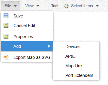
The Add submenu is available, from which you can add Devices, APs, Map Links, and Port Extenders to the map. Edit mode also allows you to manipulate the existing Devices, APs, Map Links, and Port Extenders currently displayed on the map. Select Cancel Edit to exit Edit mode. If you made any changes to the map, a dialog box appears from which you can choose to save the changes or exit Edit mode without saving your changes.
View Menu
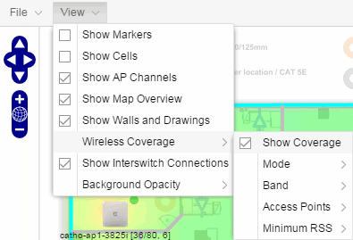
The View menu allows you to show or hide parts of your map. The options in the View menu do not change the information in the map, only allow you to show or hide additional information.
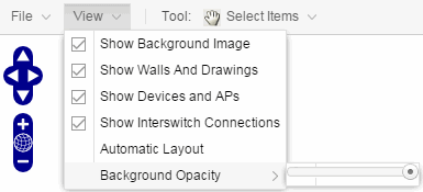
These options vary depending on the map Type and devices on the map. For example, floorplan maps display additional options, including the image you selected as the background of your map, the grid cells that establish the scale of the floorplan, the AP channels for floorplans, the map overview, the walls and drawings of the building, the wireless coverage within a floorplan, the interswitch connections, and the opacity of the background image.
| NOTE: |
Show Fabric Connect is available when at least one Fabric Connect link can be displayed on the map. |
| NOTE: | For additional information, see Advanced Map Features. |
Tool Menu
The Tool menu allows you to add lines and shapes to your maps. The following table includes descriptions of the various drawing tools accessed from the Tool menu.
| Drawing Tool | Definition |
|---|---|

|
Select Items
Select a line or shape to select it for dragging or modification. Use the yellow drag handle to reposition the item; use the blue vertex to modify the shape. Select anywhere on the map and drag to reposition the map image. |

|
Draw Polygon
Position your cursor where you want to start drawing the polygon shape. Select and draw the first line of the polygon. Select each corner of the polygon. Double-click to release the polygon line. When you are finished drawing, right-click to release the draw polygon tool. |

|
Draw Rectangle
Position the cursor where you want the rectangle. Select and drag to draw the rectangle. When you are finished drawing, right-click to release the draw rectangle tool. |

|
Add Text
Select the map to open the Enter Text window. When you are finished entering your text, select OK. Position the cursor where you want to place the text and select to add the text to your map. Use the Style menu to change the text appearance. |

|
Draw Triangle
Position the cursor where you want the triangle. Select and drag to draw the triangle. When you are finished drawing, right-click to release the draw triangle tool. |

|
Draw Line
Position your cursor where you want to start drawing the line. Select and draw the line. Select to change line direction. While drawing, press the Delete key to delete the last vertex in the line. Double-click to release the line. When you are finished drawing, right-click to release the draw line tool. |

|
Rotate Shape Select the shape you want to rotate. Use the blue handle to rotate the shape to the desired position. (You can also right-click on an image and select Rotate Shape from the menu.) |
Pan and Zoom Control
Pan Control

The Pan control allows you to move left/right and up/down in the map. You can also change the position of the map by selecting and dragging the map in any direction.
Zoom Control

The Zoom control lets you zoom in and out of the map. You can also zoom in and out of the map by rotating the mouse scroll wheel forward and backward, respectively. Selecting the globe icon in the center of the Zoom control resets the zoom and positioning for the map to the last view configured in edit mode.
| NOTE: |
Changing the location and zoom using these controls and then saving the map saves those orientation changes to the map. |
Search Field
The Search field allows you to search for a wireless client, an AP, or for a device or wired client. Enter a MAC address, IP address, hostname, user name, or AP serial number in the Search field and press Enter to start a search for a device or wired client.
Selecting the Refresh button  to the right of the Search field refreshes the map, including the position of mobile devices connected to an AP. When you select the Refresh button, the position of mobile devices updates according to their most recent location.
Selecting the Rediscover all devices on the Map button to the right of the Search field rediscovers all devices on the map. Rediscover also refreshes the Network Monitor Cache, Host Name Cache, and Historical Collection targets for all devices on the map. Rediscover can be used to update the fabric-related information from switches.
For additional information, see Performing a Search.
Viewing Alarm/Device Status
Maps display an integrated alarm/device status either to the right of a device or AP image, or incorporated as part of a map marker (if you have Show Markers selected from the map View menu). For example, the device below is down and a critical alarm is triggered (shown as a device image and as a marker).
![]()

Alarm status automatically updates every 30 seconds. Change this status refresh interval in the ExtremeCloud IQ Site Engine options (Administration > Options > OneView > Map).
-
 (Red) Critical — There is a critical alarm and the device is down.
 -
 (Orange) Error — There is a problem with limited implications on the device.
 -
 (Yellow) Warning — There is a condition that might lead to a problem on the device.
 -
 (Blue) Info — There is an information-only alarm on the device.
 -
 (Green) Clear — There are no alarms and the device is up.
Hover over a device or AP to view a pop-up that displays the IP address for a device or channels for an AP. Additionally, select the more link in the pop-up to access the Device View or additional information about the AP for a device or AP, respectively.
Accessing Device Information
There are two ways to access additional device information from a map.
Launch device information reports from a right-click menu on a device or AP in a map. The menu displays different options based on the device type. You must be in Edit mode to see the Remove From Map option.
Right-click on a device in a map and select Device View or right-click on an AP in a map and select AP Summary to open a Device View (like the example shown below) or AP PortView window where you can see a device image and other important device information.
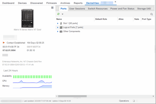
Additionally, the Device View and AP PortView windows contain tabs with additional information about the device or AP.
Link Information
Links are displayed on Topology maps as lines between devices in your network. The line colors indicate the state and status of the link:
| Color | Link State | Status |
|---|---|---|
| Green | Up | Operational |
| Red | Down | Not Operational |
| Yellow | Impaired | Partially Operational |
| Grey | Unknown | Operation Status Unknown |
| Purple | Up | Fabric Connect link with ISIS adjacency |
| Pacific Blue | Up | LLDP link with Fabric Attach |
| Navy Blue | Up | Fabric Extend link or virtual link with ISIS adjacency |
Each connection type is represented by a different line style:
- Basic links appear as thin green lines with no outlining.
- Shared links appear as basic links when the EAPS domain is not highlighted and appear as thick green lines outlined by a black solid line when you highlight the associated EAPS domain.
- Lag links also appear as thick green, but a bit darker than basic links.
- Blocked links appear as a thin green line (similar to a Basic link) outlined by a dashed black line with a red ball icon on the end of the link where the port is blocked when you highlight the associated EAPS domain. Blocked links with both ports blocked display a red ball icon on both ends of the link. Blocked links appear as basic links when the EAPS domain is not highlighted.
- Links connecting a port extender to its controlling bridge appear as dashed lines. If these links are LAG links, they appear as thick dashed lines.
- Links with active ISIS adjacency connecting Fabric Connect devices appear as a thin purple line with no outlining.
- Links with LLDP signaling active Fabric Attach appear as a thin pacific blue line with no outlining.
- Links with active ISIS adjacency connecting through Fabric Extend appear as a thin navy blue line with no outlining.


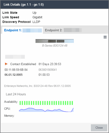
Double-clicking a connection opens the Link Details window from which you can view additional details about the network connection and the devices it links.
Network Details Section
The Network Details section is available in topology and geographic maps. The Network Details section contains multiple tabs, depending on the devices included in the map:
- Map tab — Displays information about the map
- Links tab — Displays information about the network connections between devices
- VLAN tab — Lists any virtual local area networks within the map
- MLAG tab — Lists devices configured in a multi-switch link aggregation group
- EAPS tab — Lists information about any devices configured with Extreme's Ethernet Automatic Protection Switching feature
- Extended Bridges tab — Lists any devices that support VPEX or any Extended Bridges included in the map.
- Services tab — Displays information about Fabric Connect L2 VSN and L3 VSN services
- ISIS Areas tab — Displays information about Fabric Connect ISIS areas
- ISIS Links tab — Displays information about Fabric Connect ISIS links
- Fabric Attach tab — Displays information about Fabric Attach links
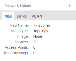
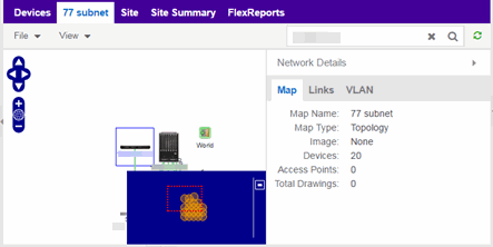
Map tab
The Map tab displays basic information about the map, including the name of the map, the map type, and the background image, as well as the number of devices, APs, and drawings on the map.
Links tab
The Links tab displays the Link Summary table for maps with one or more network connections, which contains detailed information about the network connections between devices. Selecting one of the links in the table highlights the link in the map.
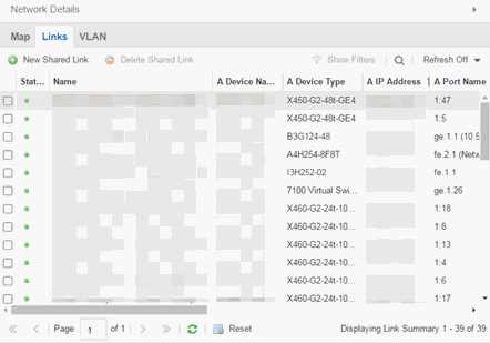
The top of the Links tab contains a search field, which allows you to find a particular Link by entering specific criteria. Additionally, you can manually browse links using the scroll bar and page navigation at the bottom of the section.
Double-clicking a link opens the Link Details window.
The top of the window displays information about the link, while information about the devices it connects are contained on two tabs, Endpoint 1 and Endpoint 2.
VLAN tab
The VLAN tab displays VLANs configured as part of devices included in the map. Columns in the VLAN tab provide additional information, including the VLAN tag, the name of the VLAN, any protocol filters applied for devices on which the VLAN is configured, and whether or not IP forwarding is enabled for the VLAN.
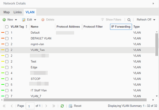
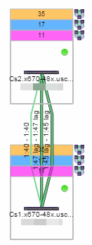
Selecting the checkbox associated with a VLAN highlights any devices to which that VLAN is assigned by surrounding the device in a box with a color-coded title bar containing the VLAN name.
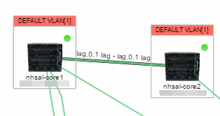
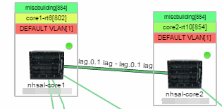
Selecting multiple VLANs assigned to the same device adds a new title bar to the box that displays the VLAN name and associated color.
Additionally, from the VLAN tab, you can create a new VLAN and create a VLAN protected by an EAPS domain via the New drop-down list or edit the ports, name, and devices associated with an existing VLAN via the Edit drop-down list. For more information, see How to Create and Edit VLANs.
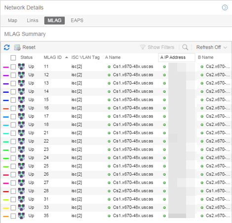
MLAG tab
The MLAG Summary tab provides a list of the MLAGs (ports combined as a common logical connection on devices) included in the map. The list provides the MLAG's status, ID, ISC VLAN tag, the names and addresses of the devices configured as part of the MLAG, and the ports on those devices assigned as part of the MLAG. Additionally, the Connected IP column displays the IP of the switch to which the MLAG is connected.
| NOTE: | One-armed MLAGs, which may be utilized in a VPEX Ring topology, will normally display an MLAG port on only one of the devices. |
Selecting the checkbox associated with an MLAG highlights any devices containing ports associated with the MLAG by surrounding the device in a box with a color-coded title bar containing the MLAG ID.
Selecting multiple MLAGs assigned to the same device adds a new title bar to the box containing the VLAN name and associated color.
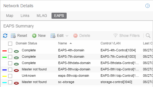
EAPS tab
The EAPS tab displays a list of the EAPS domains, including their status, name, the control VLAN name, and the IP addresses of the devices utilizing the EAPS domain.
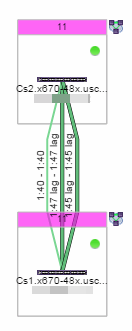
Selecting the checkbox associated with an EAPS domain highlights any devices containing ports associated with the EAPS domain by surrounding the device in a box with a color-coded title bar containing the EAPS name.
Selecting multiple EAPS domains assigned to the same device adds a new title bar to the box containing the EAPS name and associated color.
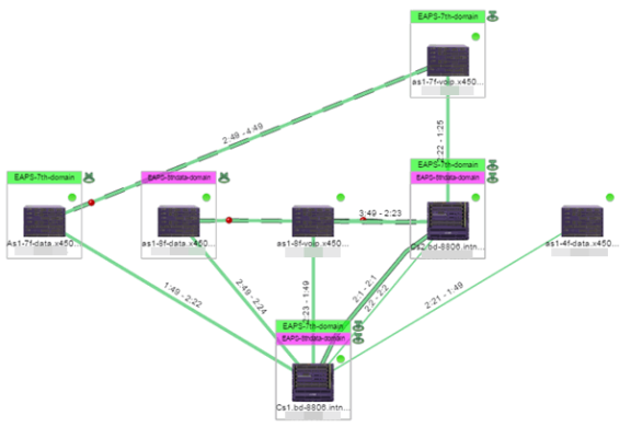
An icon next to the title bar indicates if the node is a master node, indicated by an "M" icon  , or if the node is a transit node, indicated by a "T" icon
 ![]() .
.
The color of the ring icon indicates the status of the domain:
- Green
 — Indicates all domains in which this device participates are fully operational
 - Yellow — Indicates one or more of the domains is not fully operational, but is in a transitional state or an unknown state (as when the device is SNMP unreachable)
- Red
 — Indicates one or more of the domains is not operational (the device's master domain is in a failed state or a transit node is in a "links down" state)
 - Grey — Indicates the EAPS domain is disabled
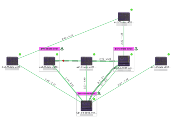
When selecting an EAPS domain, link information is also displayed. A single green line means a link that is not shared, while a dashed line between devices means the link is shared. A red dot icon on a shared link indicates the secondary link is blocked.
You can view additional details about the EAPS domain by right-clicking an EAPS domain on the EAPS tab and selecting EAPS Details to open the EAPS Detail view.
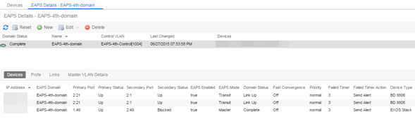
The top of the EAPS Details view displays a summary of the EAPS domain, identical to the information displayed in the EAPS tab. At the bottom of the window are three sub-tabs, which display additional information:
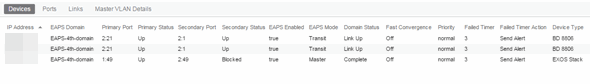
- Devices — Displays information about the devices using the EAPS domain.
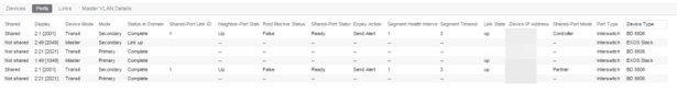
- Ports — Displays information about the shared ports associated with the EAPS domain.
- Links — Displays links between devices using the EAPS domain.
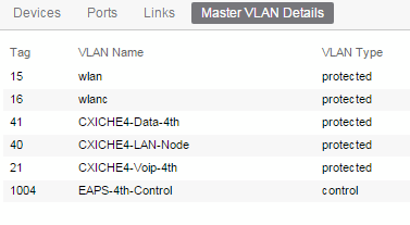
- Master VLAN Details — Displays details about the master VLAN associated with the EAPS domain.
selecting the New EAPS Domain button opens the New EAPS Domain wizard, which allows you to create a new EAPS domain. For additional information, see How to Create a New EAPS Domain.
Services tab
The Services tab displays Fabric Connect L2 VSN and L3 VSN services configured as part of devices included in the map. Columns in the Services tab provide additional information, including the Service ID, Service Name, and Service Type. The top of the Services tab contains a search field you can use to find a Service by specific criteria. You can also manually browse services using the page navigation at the bottom of the section.
Selecting the checkbox associated with a Service highlights all devices with that specific Service assigned in a box with a color-coded title bar containing the Service.
ISIS Areas tab
The ISIS Areas tab displays Fabric Connect ISIS Areas configured as part of devices included in the map. Each ISIS Area is identified by area number. The top of the ISIS Areas tab contains a search field you can use to find an ISIS Area by area number. You can also manually browse Areas using the page navigation at the bottom of the section.
Selecting the checkbox associated with an ISIS Area highlights all devices with that specific Area assigned in a box with a color-coded title bar containing the ISIS Area.
ISIS Links tab
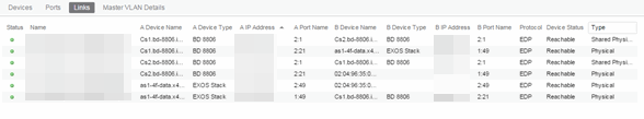
The ISIS Links tab displays the Fabric Connect Link Summary table for maps with one or more network connections, which contains detailed information about the network connections between devices. Selecting one of the links in the table highlights the link in the map. The top of the ISIS Links tab contains a search field you can use to find a Link by specific criteria. You can also manually browse Links using the page navigation at the bottom of the section.
The Unicast Path... option in the ISIS Links tab can display the Primary or Secondary Fabric Connect path between two devices running Fabric Connect. You can use the Unicast Path... menu to select the From Device, To Device, Path Type, and then click Show to display the Fabric Connect path. The path must exist and all devices on the path must be on the map used to be shown, If there is no path then the path display returns an error message.
The following details are available about the ISIS link:
-
Name
-
A Device Name
-
A Device Type
-
A IP Address
-
A Port Name
-
B Device Name
-
B Device Type
-
B IP Address
-
B Port Name
-
ISIS Area
-
A Area = the A node can be Home or Remote
-
B Area = the B node can be Home or Remote
-
A AutoSense = true if the A port is AutoSense, false if the A port is manually configured
-
B AutoSense = true if the B port is AutoSense, false if the B port is manually configured
Fabric Attach tab
The Fabric Attach tab displays the Fabric Attach Link Summary table for maps with one or more network connections, which contains detailed information about the network connections between devices. Selecting one of the links in the table highlights the link in the map. The top of the Fabric Attach tab contains a search field you can use to find a Link by specific criteria. You can also manually browse Links using the page navigation at the bottom of the section.
The following details are available about the Fabric Attach link:
-
Name
-
A Device Name
-
A Device Type
-
A IP Address
-
A Port Name
-
A Port Number
-
B Device Name
-
B Device Type
-
B IP Address
-
B Port Name
-
B Port Number
-
A Device Status
-
Type
-
LAG ID / Master
Topology and Geographic map refresh
Links and the status information in the Network Details map periodically update. An on-demand update is triggered by a Rediscover action or NBI call, or from receiving SNMP Trap or SNMP Inform information.
You can configure the device to send SNMP Traps or SNMP Informs to ExtremeCloud IQ Site Engine by enabling the Register Trap Receiver:
-
SNMPv3 Informs is the best practice and most reliable configuration.
-
SNMPv1, SNMPv2, and SNMPv3 Traps are supported.
-
For Interswitch Connections information to update near real-time, you must enable the linkDown/linkUP SNMP Traps or SNMP Inform.
-
For Fabric Connect information to update near real-time, you must enable the ISIS LSDB Traps or ISIS LSDB Informs. You can use the script Factory script to enable the ISIS LSDB Traps on VOSS devices.
| NOTE: |
Some ERS devices do not reliably send Informs. Workaround is to use Traps for these devices. |
Performing a Search
You can search for a wireless client, an AP, a device, or a wired client on the Search tab. From the tab, select Search Maps from the Search drop-down list, enter the MAC Address, IP Address, hostname, user name, AP serial number or ExtremeControl custom field information, and press Enter.
You can also search for specific wireless clients, access points, devices, and wired clients from different locations in ExtremeCloud IQ Site Engine, outlined below.
Finding a Wireless Client
From the Search Field on the Network Tab
You can locate a wireless client connected to an AP added to a map by selecting a map or the map navigation tree and use the Search field on the Network tab. To start a search for a wireless client, enter a MAC address, IP address, hostname, or user name in the map Search field and press Enter .
The search uses RSS-based (Received Signal Strength) location services to locate the wireless client and display the approximate location of the client on the map. For more information, see Advanced Map Features.
The map opens with the AP centered on the map, with a circle showing the possible area where the client is located. If that information is not available, a square is drawn around the AP last associated with the client.

From the Wireless Tab
In addition to using the Network tab Search, you can locate a wireless client from the Wireless tab. Select a client in the Clients view, right-click and select Search Maps. The map opens centered on the AP, with a circle showing the possible area where the client is located. Mouse over the client icon to see a tooltip with client information.
| NOTE: | Tooltip information is based on current data from the wireless domain unless the client icon displays a clock in the center. In that case, the tooltip information is based on historic data from the Wireless > Clients page. |
Radius Distance Calculation
The following distance calculation defines the radius of the circle displayed around the wireless client located on the map.
Path loss per meter in free space =
L1 = 20 * log (10) (f) - 28
where:
- [f] is the frequency in MHz
(Uses Source SNMP MIB dot11ExtSmtCurrentChannel
or if that value is 0, uses MIB dot11ExtSmtCurChanSelectedByAP) - [L1] is the path loss on distance of 1 meter
Radial distance for location =
d(RSS,n) = 10 ^(pTx - RSS - L1)/(10*n)
where:
- [n] is the coefficient for the environment
- [pTx] is the transmit power (dB)
- [RSS] is the Received Signal Strength
- [d] is the distance in meters
Finding an Access Point
From the Wireless Tab
You can locate an AP from the Access Points table in the Wireless tab. Select an AP in the table, right-click and select Search Maps. If a map contains the AP, the map opens with the AP centered on the map.
From the Reports Page
You can locate an AP from the Wireless > APs Summary report on the Reports tab. Select an AP in the table, right-click and select Search Maps. If a map contains the AP, the map opens with the AP centered on the map.
Finding a Device
From the Network Page Search Field
Select a map or the map navigation tree, enter an IP address or hostname for the device in the Network tab Search box and press Enter to start a search.
The search locates a device added to a map. The map centers on the device. The screen shot below shows the results for a search on a specific IP address.
Finding a Wired Client
From the Network Tab Search Field
Select a map or the map navigation tree, enter a MAC address, IP address, hostname, or user name in the Network tab Search box and press Enter to start a search for a wired client.
The search locates a wired client if the client is ExtremeControl authenticated and is connected to a switch added to a map. The map centers on the wired client.
From the Control Tab
You can also locate an ExtremeControl authenticated wired client from the Control > ExtremeControl tab. Select an end-system in the End-Systems view, right-click and select Search Maps. If the end-system is connected to a switch added to a map, the map opens with the end-system centered on the map.
Using Map Links
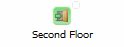
You can use map links to jump from one map to another. Map links display the name of the map and an aggregated alarm/device status for the linked map. Double-click on the link to go to the linked map. You must be in Edit mode to add a link to a map.
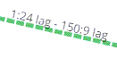
For example, the following map link lets you jump to the Second Floor map. The link is green, indicating that there are no devices with alarms on the Second Floor map.
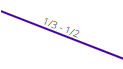
The following map link lets you jump to the First Floor map. The link is red, indicating that there is an alarm for a device on the First Floor map.
Additionally, you can use map links to display Application data based on ExtremeAnalytics network locations. For additional information, see Advanced Map Features.
For information on related help topics: