Site Engine How-tos
Discover Devices
ExtremeCloud IQ Site Engine allows you to discover the devices of your network and add them to the ExtremeCloud IQ Site Engine database.
| NOTE: | Before discovering devices, create the maps to which they belong. For additional information on creating maps, see How to Create and Edit Maps. For a list of instructions outlining the initial setup of your network in ExtremeCloud IQ Site Engine, see ExtremeCloud IQ Site Engine Initial Configuration Checklist. |
You can discover new devices based on the following criteria:
- Seed addresses for CDP, LLDP, EDP, or SONMP-compliant devices
- IP/Subnet masks
- IP Address Range
Discover automatically explores the defined network segment and creates a list of discovered devices. You can then save the discovered devices to the ExtremeCloud IQ Site Engine database, where they are displayed in the left-panel tree on the Network > Devices tab.
| NOTE: | When adding an ExtremeXOS/Switch Engine device in ExtremeCloud IQ Site Engine, enter the following commands in the device CLI:configure snmpv3 add community "private" name "private" user "v1v2c_rw" configure snmpv3 add community "public" name "public" user "v1v2c_rw" enable snmp access enable snmp access snmp-v1v2c disable snmp access snmpv3 |
To discover devices, begin by using the Site tab to configure the default settings that apply to devices you add to ExtremeCloud IQ Site Engine and then configure individual devices and add them to the ExtremeCloud IQ Site Engine database via the Discovered tab.
| NOTE: | ZTP+ enabled devices use a different device discovery process. For additional information on discovering devices using ZTP+, see ZTP+ Device Configuration in ExtremeCloud IQ Site Engine. |
Discovering Devices
- Open the Network > Devices tab.
- Select Sites from the left-panel drop-down list.
- Select the site from the left panel to which you are adding the devices.
- Select the Site tab in the right-panel.
- Select the Discover tab.
- Select the Add button in the Addresses list to open the Add Address window.
- Select Subnet, Seed Address, or Address Range in the Discover Type drop-down list.
- Enter the Subnet, Seed Address, or Start Address and End Address, depending on the Discover Type you select.
- Subnet — Enter the IP address and subnet in the following format: IP Address/Subnet Mask
- The IP Address must be one of the hosts in the subnet.
- A / is required between the IP Address and Subnet Mask.
- The Subnet Mask must use CIDR or dotted decimal notation.
NOTE: When using dotted decimal notation, the network bits must be contiguous ones and the host bits must be contiguous zeros. - Seed Address — Enter the seed address for CDP, LLDP, EDP, SONMP-compliant devices.
- Address Range — Enter the Start Address and End Address for the IP addresses in the same address range.
- Subnet — Enter the IP address and subnet in the following format: IP Address/Subnet Mask
- Select the Add button in the Profiles section of the window to open the Add Profile window. Select New in the drop-down list to create SNMP and CLI credentials for the profile and select the Save button.
Profiles allow you to configure different sets of SNMP and CLI credentials for read access, write access, and maximum access. After you create profiles, assign them to devices to allow users appropriate access based on the credentials they use for a device. - Select the profiles you want the devices on your network to Accept or Reject using the Profiles list.
For additional information about profiles, see Profiles tab. - Select the Automatically Add Devices checkbox to automatically add the devices to ExtremeCloud IQ Site Engine and configure any other appropriate actions for your devices in the Device Actions section of the window.
- Repeat the process for all devices added to this site.
For additional information about sites, see Site tab. - Select Save.
- Select Discover.
- Select the Clock icon in the Top menu to open the Operations table at the bottom of the ExtremeCloud IQ Site Engine window to monitor the progress of the device discovery.
- Access the Network > Discovered tab.
- Configure and add any devices displayed to ExtremeCloud IQ Site Engine:
- If you selected Automatically Add Devices, devices display on the Discovered tab only if they require additional attention (for example, devices are potential duplicates of another device). Configure the devices appropriately and add them to ExtremeCloud IQ Site Engine.
- If you did not select Automatically Add Devices, all devices are staged on the Discovered tab before being added to ExtremeCloud IQ Site Engine. Follow the steps in the Adding Devices section to complete the process of adding your devices to ExtremeCloud IQ Site Engine.
| NOTE: | ExtremeCloud IQ Site Engine only allows a subnet search of a 16-bit mask or higher when discovering devices. |
| NOTE: | When Automatically Add Devices is selected, devices are automatically added to ExtremeCloud IQ Site Engine and display in the Devices list on the Network > Devices tab. When Automatically Add Devices is not selected, devices are displayed on the Network > Discovered tab and require you to manually add them. |
| NOTE: | The devices displayed on this tab vary depending on whether you selected Automatically Add Devices in Step 11. |
Adding Devices
If you did not select Automatically Add Devices in Step 11, use the Discovered tab to manually add the discovered devices to ExtremeCloud IQ Site Engine.
- Open the Network > Discovered tab in ExtremeCloud IQ Site Engine.
- Select the devices you want to add to the ExtremeCloud IQ Site Engine database and select the Add Devices button. The Add Devices window opens.
The window is populated with the information you entered on the Site tab. - Enter any device-specific information, or change information that does not match the device defaults set on the Site tab.
- Select the Add button.
The devices are added to the ExtremeCloud IQ Site Engine database and move from the Network > Discovered tab to the Network > Devices tab.
Add Users
Users are given access to parts of ExtremeCloud IQ Site Engine based on the authorization group to which they are assigned. Assign a set of capabilities for each authorization group and then add users to each authorization group depending on the capabilities they require.
| NOTE: | This topic assumes devices are already added to the ExtremeCloud IQ Site Engine database. For additional information on discovering and adding devices, see How to Discover Devices in ExtremeCloud IQ Site Engine. For a list of instructions outlining the initial setup of your network in ExtremeCloud IQ Site Engine, see ExtremeCloud IQ Site Engine Initial Configuration Checklist. |
When you first log into ExtremeCloud IQ Site Engine the Administrator access through which you are currently logged in is the only set of user credentials.
This topic describes the process for adding users to ExtremeCloud IQ Site Engine, which is accomplished by performing the following steps:
| IMPORTANT: | ExtremeCloud IQ Site Engine does not save passwords. Users you create are authenticated against the Operating System, the RADIUS server, or the LDAP server, depending on the authentication method you select. |
Create Authorization Groups
First, create authorization groups for each group of ExtremeCloud IQ Site Engine users.
- Access the Administration > Users tab.
- Select the Acquire Lock button in the Users/Groups Access section at the top of the tab.
This button locks access to the tab for all other users and enables you to make changes to the authorization groups and authorized users. - Select the Add button in the Authorization Groups section at the bottom of the tab.
- Enter the appropriate information for each authorization group using ExtremeCloud IQ Site Engine.
The Capability section of the window enables you to expand each capability tree by selecting the arrow to the left of the checkbox to display more specific tasks. Select only those that apply to each user group. Additionally, you can search for a specific capability in the Search field above the tree. - Select the Save button to create the authorization group.
- Repeat the process to create the necessary authorization groups.
Add Users to Authorization Groups
Next, use of the Administration > Users tab to create the users who require access to ExtremeCloud IQ Site Engine and add them to an authorization group depending on the level of access they require.
- Select the Add button in the Authorized Users section.
- Enter a User Name, a Domain/Host Name (if necessary), and select the Authorization Group with the appropriate level of access for the user.
- Select the Save button to save the new user.
- Repeat the process to add all ExtremeCloud IQ Site Engine users for each authorization group.
Select the Authentication Method
Finally, use Administration > Users tab to select the method by which users authenticate when accessing ExtremeCloud IQ Site Engine.
ExtremeCloud IQ Site Engine supports three authentication methods to authenticate users: using the underlying host operating system, using a specified LDAP configuration, or using specified RADIUS servers.
- Select the Authentication Type using the drop-down list in the Authentication Method section.
The options change based on the Authentication Type selected. - Select the supplemental information based on the type selected.
- Select the Release Lock button to enable other users to make changes.
The users you added now have access to the functionality you configured for their respective authorization group.
How to Configure 2FA
- Ensure SMTP is configured and working, see SMTP Email Options.
-
Ensure NTP is configured and working.
-
Create or modify the Authorization group (Administration > User > Authorization Groups > select your group > Edit > Enable 2FA), see Authorization Group Capabilities
-
Add users to the Authorization Group (manually or through Automatic Membership Criteria).
| NOTE: |
SMTP is required if the user does not have the ability to scan a QR code in the authenticator application. The correct time is required, use a time synchronization protocol. The tested authenticator applications are Microsoft Authenticator and Google Authenticator. You cannot perform a Reset 2FA action on your own account. |
How to Pair a 2FA Authenticator App with your Account
-
Login to ExtremeCloud IQ Site Engine OneView with your user credentials.
-
The first time login provides you with a QR code you can use to pair your account with an Authenticator App. If you do not have a QR code scanner, you can enter your email address and use the 2FA recovery token in your Authenticator App.
-
Microsoft Authenticator with QR code:
-
Open Microsoft Authenticator.
-
Select the QR code icon.
-
Scan the QR code provided from your first log in to ExtremeCloud IQ Site Engine.
-
-
Microsoft Authenticator with 2FA recovery token:
-
Open Microsoft Authenticator.
-
Select the QR code icon.
-
Select Enter code manually.
-
Select Other (Google, Facebook, etc.)
-
Enter an account name in the Account name field. For example, "Site Engine - Production".
-
Enter the 2FA recovery token in the Secret key field.
-
Select Finish.
-
-
Google Authenticator with QR code:
-
Open Google Authenticator.
-
Select Add a code.
-
Select Scan a QR code.
-
Scan the QR code provided from your first log in to ExtremeCloud IQ Site Engine.
-
-
Google Authenticator with 2FA recovery token:
-
Open Google Authenticator.
-
Select Add a code.
-
Select Enter a setup key.
-
Enter an account name in the Account name field. For example "Site Engine - Production".
-
Enter the 2FA recovery token in the Your key field.
-
Keep Key type as Time based.
-
Select Add.
-
-
-
After the Authenticator App is configured, select Next in the ExtremeCloud IQ Site Engine OneView.
-
In OneView, Enter the code provided by your paired Authenticator App.
How to Reset 2FA
Perform the following procedure to reset 2FA for a user (Authenticator App was uninstalled)
-
Login to ExtremeCloud IQ Site Engine OneView with administrator credentials.
-
Select Administration > User > Authorized Users > select the user > Reset 2FA.
-
Instruct the user to login and pair a 2FA Authenticator App with their account.
You can compare archived device configurations in ExtremeCloud IQ Site Engine by using either the Network > Devices tab or the Archive Details Report available in the Network > Reports tab.
In order to perform the compare configuration operation, you must be a member of an authorization group with the Inventory Manager > Configuration Archive Management > View/Compare Configurations capability.
This Help topic provides the following information:
Selecting the Files to Compare
Select the files to compare using either the Network tab or the Reports tab.
From the Network tab:
Use the Network tab to compare the last two archived configuration files for a device.
Select a device in the table and use either the Menu icon ( ) or the right-click menu off the device to select More Actions > Compare Last Configurations.
From the Reports tab:
Use the Reports tab to compare two configuration files selected from all archived files for the device.
Select the Device > Device Archives report. Select the Archive Details tab in the right panel and then select the Archives by Device sub-tab.
The tab displays all the ExtremeCloud IQ Site Engine archives by device IP address. Select two files to compare and select Compare Configuration.
Comparing the Files
The Configuration File Compare window displays the files in two panels. Titles over each file show the archive name that contains the configuration file, the date, and the IP address of the device from which you create the configuration file.
Scroll through the two files to view file differences. Typically, the newer file displays in the right panel. You can use the "Swap sides" option to swap the files. In the left panel, strikethrough text highlighted in red represents text that is changed or deleted. In the right panel, blue highlighting represents text that is added.
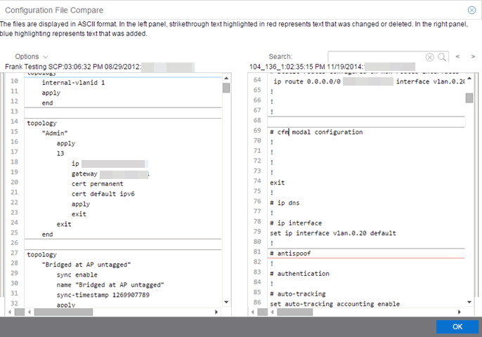
Use the toolbar Options menu to control the look of the display window:
- Enable line numbers displays line numbers alongside the text.
- Wrap lines shows all the text in the column and removes the horizontal scroll bars.
- Enable side bars shows where the text differences are in the whole file.
- Swap sides swaps the files contained in the left and right panels.
| TIP: | Removing line numbers and side bars may speed up the display of larger files. |
Use the Search field in the toolbar to perform a search in the panel side that is selected by the cursor. Use the forward and back arrows to search for the next or previous instance of the search term.
Device View is an ExtremeCloud IQ Site Engine component that provides a wide range of analysis and troubleshooting information for your network wired and wireless devices, including a device summary, FlexViews, and ExtremeCloud IQ Site Engine reports.
The primary launch point for Device View is from the Network tab. Device View can also be launched from other locations in ExtremeCloud IQ Site Engine.
This Help topic provides the following Device View information:
Requirements
Access Requirements
Access to Device View reports is determined by the user's membership in an ExtremeCloud IQ Site Engine authorization group and the group's assigned capabilities. The following list shows the capabilities required for full access to all the Device View reports.
- XIQ-SE OneView > Access OneView
- XIQ-SE OneView > Access OneView Reports
- XIQ-SE OneView > Events and Alarms > OneView Event Log Access
- XIQ-SE OneView > FlexView > OneView FlexView Read Access
Data Collection Requirements
Device View reports require that historical data collection is enabled for the device. For information on configuring data collection, see Collect Device Statistics in the Devices section of the ExtremeCloud IQ Site Engine User Guide.
Device View Panels
The Device View is comprised of a left-panel device summary, and a selection of tabbed panels that display FlexViews and reports based on the device family.
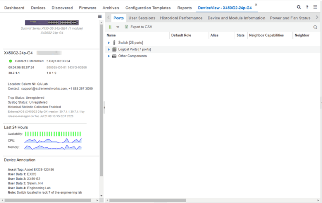
Left-Panel Device Summary
The left-panel device summary view (shown below) is displayed in each Device View report.
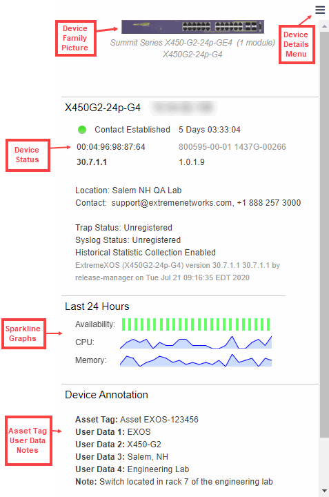
Each device summary view includes:
- Device Family Picture — A generic device family picture for the device.
- Device Status — Indicates the alarm/device status for the device. The icon color indicates the severity of the most severe alarm on the device. A red icon indicates a critical alarm or the device is down. A green icon indicates that there are no alarms and the device is up.
- Sparkline Graphs — Provides network trends in dense, succinct charts that present report data in an easy to read, condensed format. You must have Historical Statistic Collection enabled in order to see the Sparkline graphs and other report data. If Historical Statistic Collection is not enabled, you will see a line that says, "Historical Statistic Collection Disabled." For information on configuring data collection, see Collect Device Statistics in the Devices section of the ExtremeCloud IQ Site Engine User Guide.
- Asset Tag, User Data, Notes - Displays the Asset Tag, User Data and notes about the device. This data is only displayed if you have configured these values in ExtremeCloud IQ Site Engine.
- Firmware Updates Available — If there are new firmware releases available for the device (based on the results from the
latest Check for Firmware Updates operation), the Firmware Update icon
 displays. Right-click on the icon to open
a window listing the current available firmware releases with links to download
the firmware.
displays. Right-click on the icon to open
a window listing the current available firmware releases with links to download
the firmware. - Device Details Menu — Select the Menu icon (
 ) in the upper right corner to access additional device reports.
Right-Panel Device Summary
The following tabs and reports are available in the Device View. The reports displayed in a Device View vary according to the selected device. For most reports, right-click a device in the table to export the table details or details about the selected device to a .csv report.
- Ports
- Use the Ports report to view details about the ports and other components associated with the Device Family. The following columns are included in the Ports report:
- Name - The name assigned to the port
- Default Role - The policy role assigned to the selected port.
- Alias - An alternate name for the port.
- Stats - Displays whether statistics collection is enabled or disabled on the port. A black check indicates that historical collection is enabled, and a blue check indicates that threshold alarms collection (formerly monitor collection) is enabled.
- Neighbor Capabilities - Displays capabilities for neighbor ports.
- Neighbor - Displays neighbor details from CDP/EDP/LLDP. Place your mouse over the column to see the protocol type.
- Port Speed - Displays the speed of the port
- PVID - The port's VLAN ID.
- VLANs - Displays the name of the VLAN.
- Description - A description of the port.
- Port Type Details - Displays the port type and other information about the port type.
- Serial Number - Displays the port's serial number.
- Select an entry in the table, expand to display a port, and right-click to open the following drop-down list:
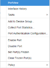
- PortView - Access PortView for that port.
- Interface History - view interface history including interface utilization, availability, and bandwidth/packets/flows statistics (Flows stats display only for S/K series and PF-FC-180 devices).
- Add to Device Group - Use to select a Device Group to which you will add the port.
NOTES: Right-clicking ports and selecting Add to Device Group opens the Add to Device Group window, which allows you to select a device group to which to add the selected ports.
Right-click a port and select the Application Telemetry menu to view the Interface Top Applications Treemap or Top Clients by Interface report for the port. If Application Telemetry is not enabled on the device, the Application Telemetry menu does not display.
Only VLANs to which ports are assigned are displayed in this report. Additionally, VLAN reports for ExtremeXOS/Switch Engine devices may display duplicate VLANs as VLANs are assigned by slot.
- Collect Port Statistics - Opens a window from which you can select your statistics collection mode (Historical, Threshold Alarms), or disable statistics collection.
- In Historical mode, port statistics are saved to the database and aggregated over time, for use in reports. The statistics are also used for threshold alarms configured in the Console Alarms Manager. In the Active Threshold Alarm Summary box, you can see all active threshold alarms configured in the Console Alarms Manager that use these statistics.
- In Threshold Alarms (formerly Monitor) mode, port statistics are saved for one hour and then dropped. You can use these statistics for threshold alarms, but not for ExtremeCloud IQ Site Engine reporting. In the Active Threshold Alarm Summary box, you can see all active threshold alarms configured in the Alarms and Events tab that use these statistics. (Note that you do not see the Threshold Alarms mode option if you have disabled threshold alarms collection in the OneView Collector Advanced Settings in Administration > Options.)
- Disable — Select this check box to disable statistic collection mode.
- Port Authentication Configuration - Access the Authentication Configuration for the port.
- Enable Port - Enables the port for the device.
- Disable Port - Disables the port for the device.
- Set Port(s) Frozen - Select to freeze the selected port.
- Clear Frozen Port(s) - Select to clear the selected frozen port.
- Policy - Use to create policy profiles, called roles, that are assigned
to the ports in your network.
NOTE: Enabling Historical Statistics Collection may use substantial disk space.
- MAC Addresses
- Device Logs
- Alarms
- Events
- Archives
- User Sessions
- Historical Performance
- Switch Resources
- Device and Module Information
- Controller History
- Power and Fan Status
- Active Access Points
- Storage Utilization
- Process Utilization
- WLAN Services
- CPU and Process Utilization
- VLAN
- Active Clients
- IP Traffic Summary
- MLAG
- Alarms and Events
- VPLS
Launching Device View
Device View can be launched from a variety of locations in ExtremeCloud IQ Site Engine.
Network Tab
The primary launch point for Device View is from the Network tab.
- Open the Network > Devices tab.
- Place your mouse over the first column and select the Device View icon
 .
. - The Device View opens as a separate tab.
Control Tab
Use the following steps to launch Device View from the Control tab.
- Open the Control > Dashboard tab.
- Select the System view.
- In the Engine Information report, select an engine IP address to open a Device View for the engine.
ExtremeCloud IQ Site Engine Maps
Use the following steps to launch Device View from a map.
- Open ExtremeCloud IQ Site Engine Maps and select a map.
- In the map, right-click on a device icon and select Device View.
Search
Use the following steps to launch Device View from the Search tab.
- Open Search and search for a device.
- In the Overview, right-click on the device icon and select Device View.
Use ExtremeCloud IQ Site Engine to upgrade device firmware for your Extreme Networks devices.
| NOTE: | Prior to upgrading firmware, you must access the Extreme Networks website to obtain information about the latest Extreme Networks firmware releases available for download. |
|---|
You can upgrade firmware in one of three ways:
You must be a member of an authorization group that includes Inventory Manager > Firmware/Boot PROM Management > Firmware/Boot PROM Upgrade Wizard capability to see this menu option.
Upgrading for a Device
To upgrade firmware for a particular device:
- Open the Network tab.
- Select the Devices tab.
- Select All Devices from the left-panel drop-down list, or select a Map or Site, depending on the location of the device you are upgrading.
- Select the Devices tab in the right-panel.
- Select the devices for which you are upgrading firmware in the Devices table in the right-hand panel.
-
Select the Menu icon (
) or right-click in the Devices list. - Select Upgrade Firmware.
NOTE: You can also right-click a single device in the left-panel and select Upgrade Firmware. - Select one or more devices and select Assign Image.
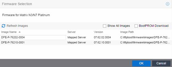
- Select the Show All Images checkbox to show all available firmware images.
- Select the firmware image to download to the device.
- After the upgrade operation completes, verify the boot PROM and firmware images on the device are compatible. Refer to the boot PROM and firmware release notes for more information. To upgrade the boot PROM, select the BootPROM Download checkbox in the Firmware Selection window. This clears any images already assigned and only displays boot PROM images for selection.
- Select OK.
- Repeat the process for all of the devices in the Upgrade Firmware window.
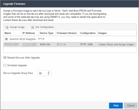
- Select the Restart Devices After Upgrade checkbox to automatically restart devices that support restarting immediately after upgrading the firmware image.
- Select the Schedule Upgrade checkbox to run the firmware image upgrade at a future date. Selecting this checkbox displays additional fields where you can configure the scheduled upgrade.
- Name — The name for the scheduled upgrade. The default name automatically populates with the creation date and time of the firmware upgrade.
- Select Date — The date and time the upgrade automatically runs. Enter a date in the mm-dd-yyyy format or select the Calendar icon
 to open a monthly calendar from which you can select the date of the upgrade. Enter the time for the scheduled upgrade or select the drop-down arrow to select the time from a drop-down list.
 - Abort on Failure — Selecting this checkbox causes the upgrade to terminate in the event it is not successful.
- Enter the number of downloads upgraded simultaneously in the Device Upgrade Group Size field. Enter a value of 1 to have the downloads performed serially (one device at a time).
- Select Start if you are upgrading the firmware immediately or Schedule if the upgrade is scheduled for a future date.
Note: To view or cancel a scheduled firmware upgrade, select Tasks > Scheduled Tasks. - If upgrading the firmware image immediately, a progress column appears on the Upgrade Firmware window. When the upgrade is complete, a Status section appears, displaying whether the upgrade occurred successfully.
- Select Close.
The Upgrade Firmware window opens, displaying the devices you selected grouped by device family.
The Firmware Selection window opens, displaying the firmware versions compatible with the device type.
| NOTE: | Right-click the device in the Upgrade Firmware window to configure how the firmware is downloaded and installed on the device (e.g. to change the server from which the firmware image is downloaded, the file transfer method, or the MIB or script used to download the firmware image). |
| NOTES: | Selecting the Restart Devices After Upgrade checkbox displays the Supports Restart column in the Upgrade Firmware window. A check mark indicates devices that support this functionality. You can also restart a device manually in the Restart Devices window, accessible from the Network tab in ExtremeCloud IQ Site Engine by right-clicking the device and selecting More Actions > Restart Device option. |
Upgrading for a Device Type
To upgrade the firmware for all devices of a particular device type:
- Open the Network tab.
- Select the Firmware tab.
- Select the device type from the Firmware tree in the left panel.
- Upload the firmware or boot PROM image, if necessary.
- Select the Upload button to open the Upload Firmware to Server window from which you can save image files to the ExtremeCloud IQ Site Engine server.
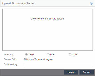
- Drag the file or files into the box in the main part of the window or select the box to open a window from which you can navigate to the appropriate directory.
- Select TFTP, FTP, or SCP to indicate whether you are upgrading the firmware or boot PROM image using a TFTP, FTP, or SCP server, respectively.
- Type the Subdirectory within the Server Path where the firmware or boot PROM images are uploaded.
- Select the Upload button.
A status bar displays over the file icon and a check mark indicates when the upload is complete. Anyone with access to ExtremeCloud IQ Site Engine is now able to download the image file to a device.
- Select the Upload button to open the Upload Firmware to Server window from which you can save image files to the ExtremeCloud IQ Site Engine server.
- Right-click the firmware or boot PROM image from the Device Type Images section of the window and select Assign Firmware from the menu.
The Assign Firmware to One or More Device Types window appears.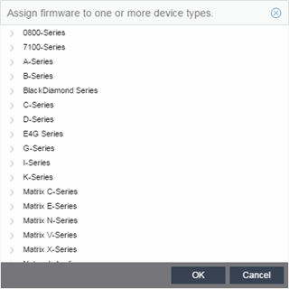
- Select the device type on which you are assigning the firmware or boot PROM image.
- Select OK.
If you did not select Restart Devices After Upgrade, restart your devices.
Upgrading for Fabric Manager
To upgrade the firmware image for Fabric Manager, follow the instructions in Upgrading Fabric Manager.
Restart a Device
Use the Devices tab to restart a single device or multiple devices. The tab lets you restart devices that support Timed Restart as well as those devices that do not. Timed Restart lets you configure your restart operation with a time delay, so that the actual device restarts take place at a later time.
To restart a device:
- Access the Network > Devices tab.
- Use the left-panel drop-down list to select All Devices, Maps, or Sites, depending on the devices you are restarting. You can also use the drop-down list to select how the devices are organized (e.g. by IP address, by Device Type).
- Select the Devices tab in the right-panel.
- Select the device or devices you want to restart (using the Ctrl or Shift keys).
- Select the Menu icon () or right-click in the Devices list.
- Select More Actions > Restart Device.
NOTE: You can also right-click a single device in the left-panel and select More Actions > Restart Device.
The Restart Devices window displays. - Select the devices you want to restart by selecting the checkbox in the Selected column.
NOTE: The Restart Devices window contains additional fields for devices that support timed restart. - Select the date and time you want to restart the device for devices that support timed restart using the Restart Time fields. This field defaults to the current date and time, so to restart the devices now, do not change this field.
- Select Start to initiate the device restarts or to schedule a future device restart. Elapsed Time displays the elapsed time since beginning the restart process.
- Select Finish to close the window
Add a New Regime (Legacy)
The Compliance tab provides you with regimes that include predefined audit tests. You can also create your own regimes, composed of audit tests you can copy from existing regimes, or configure yourself.
To create a new regime:
- Open the Compliance > Audit Tests tab.
- Select the Menu icon () and select Add > Regime.
The Create Regime window displays. - Enter a Regime Name, describing the overarching standard or regulation against which you are testing compliance.
- Enter a Description for the regime, if necessary.
- Select Test Wireless Events to include wireless events in the ExtremeCompliance audit.
NOTE: Because of the number of wireless events potentially stored by ExtremeCloud IQ Site Engine, wireless events are not included in an ExtremeCompliance audit the first time it is run. When the audit is run the first time, older wireless events are moved, so older events are not included in the results. - Select Save.
- Copy existing audit tests to the new regime, if necessary.
- Right-click the audit test in left-panel and selecting Copy Audit Test.
The Copy Audit Test window displays. - Enter a new name for the audit test, if necessary.
- Select the new regime in the Regime drop-down list.
- Select the device type to which the audit test applies in the Device Type drop-down list.
- Select Copy.
- Right-click the audit test in left-panel and selecting Copy Audit Test.
- Create your own audit tests.
- Select the Menu icon () and select Add > Audit Test.
- Complete the fields in the Audit Test Editor tab to test for a device configuration.
- Complete the fields in the Dependent Tests tab, if necessary.
- Select Save.
- Select the Menu icon (
Your custom regime is now available on the Compliance tab.
Using Extreme Networks' ZTP+ (Zero Touch Provisioning Plus) functionality, you can quickly add new ZTP+-enabled devices to your network and configure them in ExtremeCloud IQ Site Engine.
Typically, when adding a new device to the network, a network administrator connects a console cable to the device to access the local console and manually configure the device.
| IMPORTANT: | Stacked ExtremeXOS/Switch Engine systems must be running ExtremeXOS/Switch Engine version 30.3 or later to support ZTP+ configuration. |
|---|
In ExtremeCloud IQ Site Engine, new devices are automatically discovered on the network the moment they are connected. ZTP+-enabled devices send information to ExtremeCloud IQ Site Engine automatically, including the serial number, the number and speed of the ports, and the firmware version. When a ZTP+-enabled device is connected, you can add it to ExtremeCloud IQ Site Engine with minimal server configuration. In addition, the latest updates are automatically downloaded to the new device. This process minimizes the amount of time needed to configure a new device and deploy it on the network.
Prerequisites
Before connecting your devices, configure the following:
- Select the Reference Firmware Image Location
- Default Device Configuration in ExtremeCloud IQ Site Engine
- Download XMODs (ExtremeXOS/Switch Engine devices only)
- General Network Configuration
- NOS Persona Change from Switch Engine to Fabric Engine
Select the Reference Firmware Image Location
You can configure ExtremeCloud IQ Site Engine to automatically update your device's firmware and application versions. When upgrading the firmware image on your device, access the appropriate firmware image for your version from ExtremeNetworks.com and save it on your server to a directory you configure in ExtremeCloud IQ Site Engine. After the firmware image is saved on the ExtremeCloud IQ Site Engine server, it is available in ExtremeCloud IQ Site Engine and can be downloaded to the device.
For the device to recognize a new version is available, the firmware image must be downloaded from ExtremeNetworks.com to your server and saved in a directory you configure in ExtremeCloud IQ Site Engine.
To configure the file transfer directory:
- Access the Options tab.
- Select Inventory Manager in the left panel.
- Enter the Firmware Directory Path in either the FTP Server Properties, SCP Server Properties, or TFTP Properties section of the right panel, depending on the file transfer settings used.
- Download the latest firmware image for your device from ExtremeNetworks.com and save it in the specified directory.
When you download the firmware image from ExtremeNetworks.com and save it on the ExtremeCloud IQ Site Engine server, use the Firmware tab in ExtremeCloud IQ Site Engine to download the image from the ExtremeCloud IQ Site Engine server to the device.
- Access the Network > Firmware tab.
- Expand the Device Type navigation tree in the left-panel for the device family you are configuring and select the folder for the type of device.
- Right-click the firmware file you downloaded (specified in the section above) and select Set as Reference Image.
Your device automatically updates with this firmware image when it restarts and is logged in the Event log with a Category of Inventory.
Default Device Configuration in ExtremeCloud IQ Site Engine
Before connecting your devices, you can configure the default settings that ExtremeCloud IQ Site Engine applies to all devices you add to the network. This is accomplished using the Site tab.
- Access the Devices tab in ExtremeCloud IQ Site Engine.
- Expand the World Site navigation tree and select the map in the left panel into which you are adding the devices.
- Select the Site tab in the right panel.
- Select the Automatically Add Devices checkbox in the Discovered Device Actions section and any other actions you want to occur on your devices discovered in ExtremeCloud IQ Site Engine.
G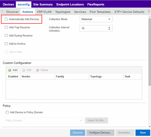
- Use the Custom Configuration section to automatically run a script on devices being added to the site, if necessary.
CAUTION: If the script or workflow task selected for the Custom Configuration restarts the device, other actions selected to execute during discovery might not execute (for example, Add Trap Receiver). - Select Add Device to Policy Domain or Add Device toExtremeControlEngine Group to automatically add devices being added to the site to a Policy Domain or ExtremeControlengine group.
- Add the VLANs that are used on your devices on the VLAN Definition tab by selecting the Add button and entering the Name and VID.
- Use the Port Templates tab to create a port configuration, if necessary.
- Enter the Gateway Address, Domain Name, and DNS Server address on the ZTP+ Device Defaults tab. Additionally, you can configure the NTP Server address and select the protocols to enable on your devices, if necessary.
- Select Save.
The default configuration for this site is complete and any devices you discover with this site selected use this criteria.
Download XMODs (ExtremeXOS/Switch Engine devices only)
XMODs are files that work in conjunction with firmware image upgrades to enhance ZTP+ functionality on ExtremeXOS/Switch Engine devices as well as provide bug fixes for existing features. Like firmware image upgrades, they are posted by Extreme Networks on github and ExtremeNetworks.com. Save XMODs in the directory you specify in the Firmware Directory Path field. Do not set an XMOD as the reference image.
| IMPORTANT: | ExtremeXOS devices running version 21.1.1.4 require an update to the CloudConnector XMOD for ZTP+ to function properly. Save the most recent XMOD in the Firmware Directory Path specified above to update the device, allowing ZTP+ to function as intended. Recent ExtremeXOS/Switch Engine firmware images already include the CloudConnector XMOD, and no updates are required for ZTP+ functionality If multiple CloudConnector XMOD files exist in the same directory on the ExtremeCloud IQ Site Engine server as the reference image, ExtremeCloud IQ Site Engine downloads the XMOD file with the higher version number on the device. |
General Network Configuration
In order for the switch to communicate to the ExtremeCloud IQ Site Engine server:
- The DHCP Server needs to return a DNS Server and Domain Name to the ZTP+ device.
- The DNS Server needs to map the name extremecontrol.<domain-name> to the IP address of the ExtremeCloud IQ Site Engine server.
NOS Persona Change from Switch Engine to Fabric Engine
You can configure the ExtremeCloud IQ Site Engine to change the persona of a switch from Switch Engine to Fabric Engine during the ZTP+ process. For a persona change to occur, you must:
- Upload the Fabric Engine firmware to both the TFTP and SFTP directories (Network > Firmware > Upload...)
- Configure the Fabric Engine firmware in the SFTP directory as a reference image
- Configure the NOS Persona Change field as To Fabric Engine for a specific site, or manually during the ZTP+ process
Adding the Device to the ExtremeCloud IQ Site Engine Database
Now that the default criteria is configured for devices added to the World Site and you set up the DHCP and DNS servers allowing the device to communicate with the ExtremeCloud IQ Site Engine database, connect the device and add it to ExtremeCloud IQ Site Engine.
- Connect the device to your network.
ZTP+ enabled devices communicate with ExtremeCloud IQ Site Engine securely via an HTTPS connection and transmit information to ExtremeCloud IQ Site Engine, including the serial number, firmware version, MAC address, operating system, and port information. ExtremeCloud IQ Site Engine determines the status of devices and if new updates are available in the Firmware tab and set as Reference images, they are automatically installed. - Open the Discovered tab in ExtremeCloud IQ Site Engine.
The device is listed with a Status of ZTP+ Pending Edit, indicating the device configuration needs to be edited before adding it to the ExtremeCloud IQ Site Engine server.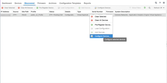
- Select the device and select the Configure Devices button.
The Configure Device window opens.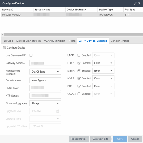
- Select the Default Site for the device.
- Select the Poll Group for the device, which indicates the frequency with which ExtremeCloud IQ Site Engine checks for new configurations or updates.
- Select the appropriate Poll Type, which determines how devices are managed on your network:
- ZTP Plus — Devices are polled using ZTP+ functionality.
- SNMP — After devices are added to ExtremeCloud IQ Site Engine via ZTP+, devices are polled using SNMP and are managed manually.
- Open the ZTP+ Device Settings tab.
- Configure the fields on the ZTP+ Device Settings tab to determine how the device is managed by ExtremeCloud IQ Site Engine using ZTP+ functionality.
- Open the Ports section of the window by selecting the section heading.
The Ports section opens, displaying the ports transmitted by the device to ExtremeCloud IQ Site Engine when connected to the network.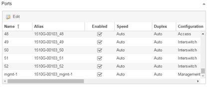
- Select a port in the list to configure the port Name, Alias, Configuration, or port VLAN ID.
You can also add and delete ports by selecting the Add and Delete buttons, respectively:- Enter the port Alias.
- Select the port Configuration, which is its role or purpose for the device.
- Access — The port provides access to end-systems.
- Interswitch — The port connects the switch to another switch.
- Management — The port is used to manage the network via ExtremeCloud IQ Site Engine.
- Enter a VLAN ID for the port in the PVID field.
- Configure the port Speed and Duplex.
- Open the ZTP+ VLAN Definition section of the window by selecting the section heading.
The ZTP+ VLAN definition section opens, containing any VLANs you configured on the Site tab.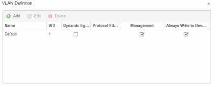
- Add any device-specific VLANs to those already included in the list by selecting the Add button.
- Change any incorrect fields in the Device, Device Annotation, or Discovered Device Actions sections.
- Select Save at the bottom of the window.
The device is added to the ExtremeCloud IQ Site Engine database and moves from the Discovered tab to the Devices tab.
| NOTES: |
If you did not select Automatically Add Devices on the Site tab, the device remains on the Discovered tab with a Status of ZTP+ Complete. Select the device, select the Add Devices button (the Add Device window appears), and select the Add button to add the device to the ExtremeCloud IQ Site Engine database. In the event a configuration is not correctly transmitted to the switch or if connectivity is lost during any part of this process, the device resets and allows the process to restart. |
The device Status (displayed on the Discovered tab) is now ZTP+ Staged, indicating ExtremeCloud IQ Site Engine will push the configuration to the device the next time the device contacts ExtremeCloud IQ Site Engine.
When ExtremeCloud IQ Site Engine pushes the configuration to the device, the device Status is ZTP+ Complete.
ExtremeCloud IQ Site Engine generates an event indicating it is upgrading a device image, when the device image is upgraded to the latest version, and when a configuration is sent to a device.
Using Extreme Networks' ZTP+ (Zero Touch Provisioning Plus) functionality, you can quickly add new ExtremeAnalyticsengines to your network and configure them in ExtremeCloud IQ Site Engine.
| IMPORTANT: |
Logging in to the engine and running the initial engine configuration script will result in the ZTP+ configuration process being shutdown. |
|---|
Once ZTP+ enabled devices are configured and connected in ExtremeCloud IQ Site Engine, you can view important data and flow collector information on the ExtremeAnalytics tab.
General Network Configuration
In order for the engine to communicate with the ExtremeCloud IQ Site Engine server:
- The DHCP Server needs to return a DNS Server and Domain Name to the ZTP+ device.
- The DNS Server needs to map the name extremecontrol.<domain-name> to the IP address of the ExtremeCloud IQ Site Engine server.
Once ExtremeCloud IQ Site Engine and the ZTP+ device are pre-configured, you can add the site definition to the ExtremeCloud IQ Site Engine database.
Adding the Device to the ExtremeCloud IQ Site Engine Database
When the default criteria is configured for devices added to the World Site and you set up the DHCP and DNS servers allowing the device to communicate with the ExtremeCloud IQ Site Engine database, connect the device and add it to the Discovered tab.
- Open the Discovered tab in ExtremeCloud IQ Site Engine.
The device is listed with a Status of ZTP+ Pending Edit, indicating the device configuration needs to be edited before adding it to the ExtremeCloud IQ Site Engine server. Add the ZTP device settings and the flow source information. - Right-click the device and select Configure Devices tab from the drop-down list.
The Configure Device window opens. - Select the ZTP+ Device Settings tab.
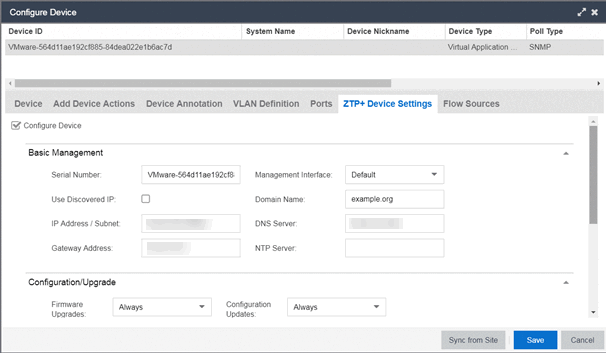
- Configure the fields on the ZTP+ Device Settings tab to determine how the ExtremeAnalyticsengine is managed by ExtremeCloud IQ Site Engine using ZTP+ functionality.
- Select the Flow Sources tab in the Configure Device window.
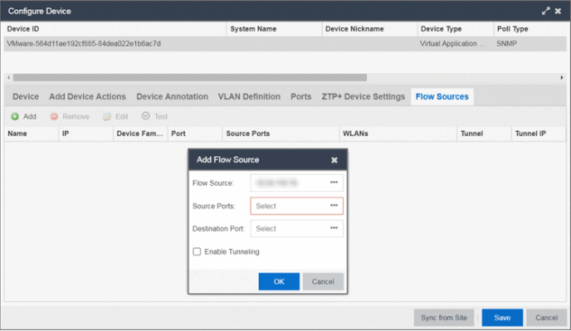
- Select the ExtremeAnalyticsengine flow information.
- Select the Add (
 ) button.
The Add Flow Source window displays. - Select FC-180 from the Flow Source drop-down list.
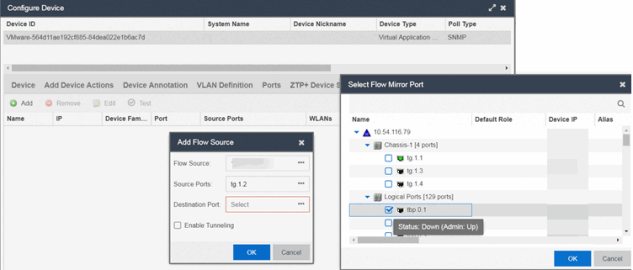
- Select the Source Ports from the drop-down list.
- Select the Destination Port from the drop-down list.
- Select the Enable Tunneling checkbox.
- Select the Tunnel IP address from the drop-down list.
- Select OK to complete the Flow Source configuration.
| NOTES: |
If you did not select Automatically Add Devices on the Site tab, the ExtremeAnalyticsengine remains on the Discovered tab with a Status of ZTP+ Complete. Select the engine, select the Add Devices button (the Add Device window appears), and select the Add button to add the engine to the ExtremeCloud IQ Site Engine database. In the event a configuration is not correctly transmitted to the switch or if connectivity is lost during any part of this process, the engine resets and allows the process to restart. |
Completing Configuration and Enforcing the Engine in ExtremeAnalytics
The engineStatus (displayed on the Discovered tab) is now ZTP+ Staged, indicating ExtremeCloud IQ Site Engine will push the configuration to the device the next time the device contacts ExtremeCloud IQ Site Engine.
Open the Configuration tab. The engine is configured with the ZTP+ enabled device and is displayed in the Overview window. Enforce the engine to complete the process.
PortView is an ExtremeCloud IQ Site Engine component that provides port analysis and troubleshooting information including NetFlow data and ExtremeControl end-system details, for your network wired and wireless devices.
The primary launch point for PortView is from the ExtremeCloud IQ Site Engine Search. Depending on the type of item you are searching for, one or more PortView tabs display with information pertaining to your search item. You can also launch PortView from other locations in ExtremeCloud IQ Site Engine.
PortView lets you:
- View a topological display of device relationships.
- Analyze flow details, applications, senders, and receivers.
- Analyze real-time status, utilization, errors, and packets for a port.
- View the map of devices to which the end-system is connected.
- Analyze historical utilization and availability for a port.
- View all end-systems attached to a port and critical end-system information.
This Help topic provides the following PortView information:
Requirements
License and Data Collection Requirements
The information provided in each report depends on the selected switch and the report data collections you configure. For information on configuring data collection, see Enable Report Data Collection.
The following chart describes the complete set of PortView reports and provides the data collection requirements for each report (if applicable). Some of these reports are available as PortView tabs, others are launched from the right-click menu in the graphical Overview report.
| PortView Report | Description | Requirements |
|---|---|---|
| Overview | Topological display of device relationships. | |
| Application Summary | View reports that present a summary of application information. | |
| Details | The tabs within the report contain the following information: Access Profile — Displays an interactive fingerprint containing information about the end-system. Select an icon to open additional details. End-System — View information about the end-system. End-System Events — View the ExtremeControl Dashboard end-system events table filtered to display all events for the end-system based on the MAC address. Health Results — Displays risk information for the selected end-system. |
Switch must have ExtremeControl authentication enabled. |
| Map | Displays the map containing the device to which the end-system is connected. |
|
| Sessions | The tabs within the report contain the following information: Interface History — Historical interface utilization and availability. Client History — Historical statistics for wired or wireless clients. End-System Events — View the ExtremeControl Dashboard end-system events table filtered to display all events for the end-system based on the MAC address. NetFlow — NetFlow data for the selected port. |
Requires active interface statistics collection. Client statistics collection must be enabled. Switch must have ExtremeControl authentication enabled. The switch must support NetFlow and flow collection must be enabled on the port. |
| Network Information | The tabs within the report contain the following information: Wireless Details — Presents controller, AP, or client information, depending on your search. Interface Details — Real-time interface status, utilization, and errors. AP History — Contains historical data for your APs. Switch Resources — Switch CPU and memory utilization statistics. Device Resources — Device CPU and memory utilization statistics. |
Requires active device statistics collection. Requires active device statistics collection. |
Access Requirements
Access to PortView reports is determined by the user's membership in an ExtremeCloud IQ Site Engine authorization group and the group's assigned capabilities. The following table lists the capabilities required for access to the different PortView reports.
| PortView Report | Required Capability |
|---|---|
| Network Information Interface History Client History Client Event History Switch History Controller History |
XIQ-SE OneView > Access OneView or XIQ-SE OneView > Access OneView and Access OneView Administration |
| Sessions > NetFlow | XIQ-SE OneView > NetFlow Read Access |
| Modify Flow Collection | XIQ-SE OneView > NetFlow Read/Write Access |
| Map | XIQ-SE OneView > Maps > Maps Read Access or Maps Read/Write Access |
| Details Sessions > End-System Events |
XIQ-SE OneView > ExtremeControl > OneView End-Systems Read Access or XIQ-SE OneView > ExtremeControl > OneView End-Systems Read/Write Access |
Launching PortView
You can launch PortView from a variety of locations in ExtremeCloud IQ Site Engine. By default, you can have five active PortView searches displayed in ExtremeCloud IQ Site Engine at one time. You can change this display limit in the Maximum PortViews Displayable field in Site Engine - General (Administration > Options > Site Engine - General > Session Limits).
| NOTE: | A single PortView search returns a maximum of five matching results. If the number of matching results exceeds five, an error message appears asking you to refine the search term and try again. |
Launching from ExtremeCloud IQ Site Engine
ExtremeCloud IQ Site Engine Search Tab
The primary launch point for PortView is from ExtremeCloud IQ Site Engine Search. The Search page provides a search field where you can enter a MAC address, IP address, host name, AP serial number, or ExtremeControl custom field information to begin searching. Depending on the type of item for which you are searching, the search results return one or more PortView tabs, with information pertaining to your search item. You can right-click on the different devices in the topology results to launch additional reports.
- Open the Search tab.
- Enter a MAC address, IP address, host name, AP serial number, or Identity and Access custom field information, and press Enter to begin the search. You can copy the IP or MAC address from another source and enter it into the Search field. For example, you can copy an end-system MAC address from the Control tab End-Systems view, and then paste the MAC address into the search field and press Enter.
- Depending on the type of item for which you are searching, the secondary navigation bar displays one or more PortView tabs, with information pertaining to your search item, similar to the search results shown below.
ExtremeCloud IQ Site Engine Interface Summary FlexView
Use the following steps to launch PortView from an ExtremeCloud IQ Site Engine Interface Summary FlexView.
- On the Network tab, select on the device Name link to open the Interface Summary FlexView.
- In the Interface Summary, select the interface Name or Alias link to open PortView.
Launching from Console
You can launch PortView from Console using any of the following methods:
- In the Port Properties tab, right-click on one or more ports and select Port Tools > PortView.
- In the Compass Results table, right-click on up to four entries and select Port Tools > PortView.
- In the Interface Summary FlexView, right-click on one or more ports and select Port Tools > PortView.
Launching from NAC Manager
You can launch the PortView ExtremeControl reports from NAC Manager using either of the following two methods:
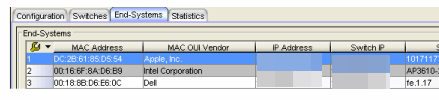
- In the End-Systems tab, right-click on an end-system in the table and select PortView from the menu.
- On the Control tab's End-Systems view, right-click the entry with the desired switch port and select PortView from the menu.
Real Capture allows real-time collection of Access Point (AP) wireless traffic for troubleshooting and problem resolution. Real Capture collects traces on the AP wireless interface and transmits them to Wireshark running on a local Windows client. It allows Wireshark to capture RF/wireless traffic as if it were running directly on the AP, providing visibility into network connectivity and performance issues. All Wireshark features are supported, including filters and I/O graphs.
| NOTE: | APs must be running firmware version 8.x or later. The AP2600 series of Access Points does not support the Real Capture feature. |
Real Capture can be enabled for each AP individually from PortView in the ExtremeCloud IQ Site Engine. When it is enabled, Real Capture runs a daemon on the AP that allows it to interface with Wireshark using port 2002 or 2003. The AP then captures all the wireless traffic (except for management traffic) originating from the AP and sends it to Wireshark for analysis.
In addition to capturing network traffic for analysis in Wireshark, the AP also collects RF information. The RADIOTAP header format delivers RF information. You must use Wireshark 1.6 or later to read the full RADIOTAP header information. For troubleshooting features like TxBF/STBC, you can enable capturing the 802.11n preamble header using the AP CLI commands.
| NOTE: | When capturing client traffic on the AP, if the topology is bridged at AP, client traffic is captured and can be analyzed in the resultant trace. However, if the topology is bridged at controller, only WASSP traffic is captured as the AP tunnels this communication back to the controller. This traffic must be sent to the Extreme Networks Support for analysis because it needs to be decoded. In this scenario, it may be better to mirror the switch port where the controller connects to the LAN. |
Configure and Use Real Capture
Use the following steps to configure and use the Real Capture feature.
- Launch ExtremeCloud IQ Site Engine.
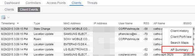
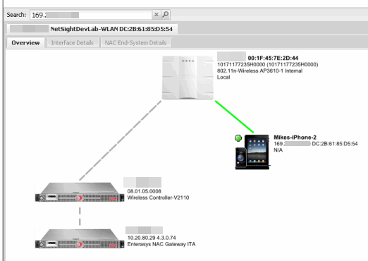
- Launch PortView for the AP from the Wireless Client Event History report.
- Select the Wireless tab and then select the Clients tab and the Client Events sub-tab. Right-click on the AP Name and select AP Summary from the menu.
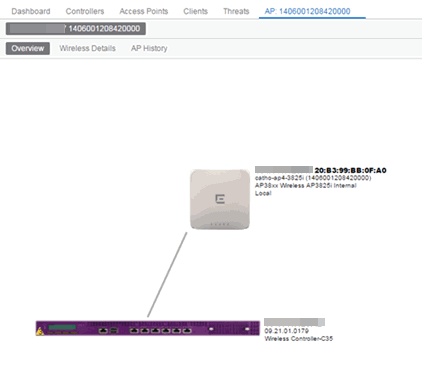
- The AP PortView opens.
NOTE: You can also launch PortView for the AP using the Search tab. Open the Search tab, enter the search criteria (MAC, IP, hostname, or AP serial number) and press Enter to display the AP PortView. - Select the Wireless tab and then select the Clients tab and the Client Events sub-tab. Right-click on the AP Name and select AP Summary from the menu.
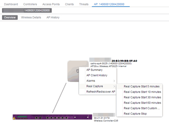
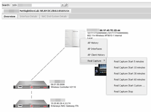
- Right-click on the AP in the PortView topology display and select Real Capture > Real Capture Start xx minutes. Select the desired amount of time to run the capture or create a custom capture duration value. If you need to, you can stop the Real Capture by selecting Real Capture Stop.
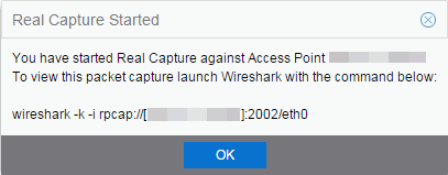
- A message appears to inform you Real Capture has started, and provides a CLI command you can use on a client on which Wireshark is installed, to launch Wireshark against the AP and view the captured traffic.
- You can also access the captured traffic in Wireshark using the following steps:
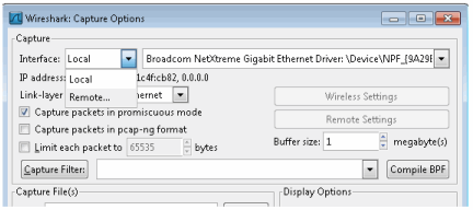
- In Wireshark, select Capture > Options from the menu bar.
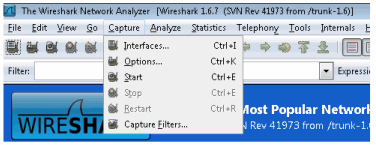
- In the Capture Options window, set the Interface value to Remote.
- The Remote Interface window appears. Enter the AP's IP address in the Host field, and the port number (2002 or 2003) in the Port field (you can see this information in the CLI command message described in step 4). In the Authentication section, select Null authentication. Select OK.
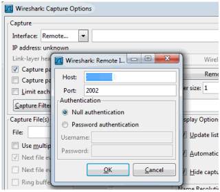
Wireshark adds the command information to the Capture options.
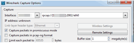
- Select OK in the Capture Options window to begin viewing the captured traffic in Wireshark. When you have the data you need, you can stop the capture and save it to a file for further diagnosis and troubleshooting.
- In Wireshark, select Capture > Options from the menu bar.
Real Capture Example
The following example shows how to use Real Capture to diagnose an end-system connection problem in NAC Manager.
The problem starts when an end-system in NAC Manager is not able to obtain an IP address.
A search is performed on the 169.x.x.x IP address.
The traffic capture is started on the AP to which the end-system is connected.
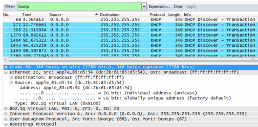
The resulting trace in Wireshark shows the end-system sending out DHCP Discover packets with no response, perhaps indicating a VLAN or network-related issue.
Restoring the Database Using the CLI
Use the instructions in this topic to restore an ExtremeCloud IQ Site Engine database backup using the CLI (command line). Restoring a database using the CLI may be necessary after making significant unwanted configuration changes.
| NOTE: |
For ExtremeCloud IQ Site Engine 24.2 and earlier, a database backup created by the Backup/Restore procedure, with Back Up Alarm, End-System Event, and Reporting Database enabled, is required prior to running the following database restore procedure. This procedure does not work if Back Up Alarm, End-System Event, and Reporting Database are disabled. In release 24.2 and earlier, the backup script is mysqlbackup_restore.sh |
|---|
The restore runs using the backup_restore script in the <install directory>/scripts directory.
To restore the backup from another instance of ExtremeCloud IQ Site Engine, the backup needs to be transferred first. The content of <install directory>/backup> including subdirectories should be transferred to the new instance. To restore the ExtremeCloud IQ Site Engine database backup:
- Ensure you are running the same version of ExtremeCloud IQ Site Engine used when creating the database backup on the ExtremeCloud IQ Site Engine server.
- Log into the system shell (via the local console or SSH) on the ExtremeCloud IQ Site Engine server as root.
- Navigate to the scripts directory:
- Enter
cd <install directory>/scripts.
- Enter
- Run the backup_restore script:
- Enter
./backup_restore.sh <full backup directory structure configured on Backup/Restore tab, including path>
(for example,./backup_restore.sh /usr/local/Extreme_Networks/NetSight/backup/xiqse_03302021/).
- Enter
| NOTE: |
If you restore a backup for troubleshooting purposes, disable the connection to ExtremeCloud IQ to prevent influencing the production statistics. The restoration script will offer you the option to disable the connection to ExtremeCloud IQ. For air gap deployment mode, the option to disable the ExtremeCloud IQ connection is not relevant. |
|---|
The database backup is restored. Devices onboarded to ExtremeCloud IQ after the backup was created become orphaned when the database restore is finished. Manual deletion of orphaned devices in ExtremeCloud IQ might be needed.
| IMPORTANT: |
The deployment mode (connected or air gap) is part of the database backup. Restoring from the backup will not change the deployment mode. The serial number is part of the database backup. Restoring the backup also restores the serial number. The air gap license file is bound to the serial number. Neither license keys nor license files are part of the database backup. In Connected deployment mode, the following sequence is recommended:
If you are restoring the backup to a clean installation, license files and license keys should be inserted into ExtremeCloud IQ Site Engine after the restore. |
Restore Device Configuration
On the Network tab, you can easily restore a device configuration to an active network device using a "cloned" configuration from an existing network device or a configuration template created on the Network > Devices tab. In addition, you also have the ability to download the latest firmware on the active device.
This Help topic provides the following information:
Preliminary Steps
Required Capabilities
In order to perform the restore configuration operation, you must be a member of an authorization group with the following capabilities.
| Required Capability |
|---|
| Inventory Manager > Firmware/Boot PROM Management > Firmware/Boot PROM Upgrade Wizard |
| Inventory Manager > Configuration Archive Management > Archive Restore Wizard |
| Inventory Manager > Configuration Templates Management > Configuration Templates Download Wizard |
| XIQ-SE Suite > Devices > Add, Discover, and Import |
Device Firmware
If you are updating the device's firmware, you must first add the new firmware version to the left-panel Firmware folder on the Network > Firmware tab. It is then available when configuring the device.
For information on obtaining firmware, contact your Extreme Networks representative, or access the firmware download library at: https://extremeportal.force.com/.
- Place your new firmware in your firmware directory. ExtremeCloud IQ Site Engine uses the default tftpboot\firmware\images directory for storing your firmware.
- In the left-panel Firmware folder, select the Refresh icon (
 ). ExtremeCloud IQ Site Engine automatically adds your new firmware to the
appropriate firmware groups in the left-panel Firmware folder.
). ExtremeCloud IQ Site Engine automatically adds your new firmware to the
appropriate firmware groups in the left-panel Firmware folder.
The new firmware version is available when configuring the device in ExtremeCloud IQ Site Engine.
Restoring a Configuration
When restoring a configuration to an active device, there are two options for selecting a configuration to use. One option is to "clone" an existing device on the network for a configuration. Another option is to use a Configuration Template you create.
Cloning a device configuration is useful when you want to use the exact same configuration on another device. If you are cloning a device configuration, you must have an existing configuration for that device archived.
Using a configuration template allows you to restore a complete or partial configuration to the device with variables you can define specifically for that device. If you are going to use a configuration template for your device, you must create the Configuration Template to use as the source configuration for a device.
Cloning a Device Configuration
When cloning a device configuration, use an existing configuration of a network device archived in ExtremeCloud IQ Site Engine. The cloned device (the archived device you are using) must not be active on the network to prevent two devices from having the same IP address on the network.
- Launch ExtremeCloud IQ Site Engine. On the Network > Devices tab, right-click on the active device and select More Actions > Restore Configuration. The Restore Configuration window opens.
- Select the Clone tab.
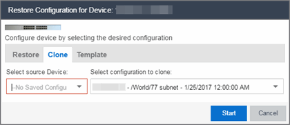
- If desired, select a new version of firmware to download to the device. (You must add the new firmware version to ExtremeCloud IQ Site Engine. For more information; see "Device Firmware".)
- Select the Device option as the Configuration Source.
- Select the source device for the configuration. The selected device must be Inactive on the network or you cannot perform the restore operation. This prevents two devices from having the same IP address on the network.
- Select the archived device configuration to clone.
- Select Start. First, the firmware is updated (if that option is selected) and then the configuration is loaded and the device is restarted.
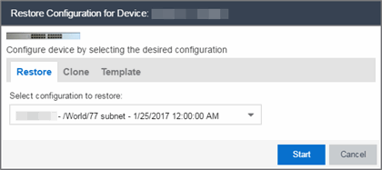
Using a Configuration Template
The following steps describe how to use a configuration template as the source configuration for a device.
- Launch ExtremeCloud IQ Site Engine. On the Network > Devices tab, right-click on the active device and select More Actions > Restore Configuration. The Restore Configuration window opens.
- Select the Template option as the Configuration Source.
- Select the appropriate template from the Template drop-down list and enter the required variables.
- Select the Profile for the new device from the drop-down list.
- Select Start. The configuration is loaded and the device is restarted.
Configuring Enhanced Netflow for Extreme Analytics and Extreme Wireless Controller Version 10.21 in ExtremeCloud IQ Site Engine
When adding a Wireless Controller as a flow source in ExtremeCloud IQ Site Engine, a mirror port is automatically created. Wireless Controllers on which a firmware version of 10.21 or higher is installed use IPFIX, so the mirror port is unnecessary.
| NOTE: | Wireless Controllers on which a firmware version lower than 10.21 is installed still require the mirror port be configured. |
To remove a mirror port on a Wireless Controller running version 10.21:
- Access the Wireless tab in ExtremeCloud IQ Site Engine.
The Wireless tab opens.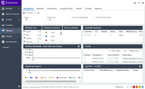
- Select the Controllers tab.
The Controllers tab opens.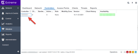
- Select the IP address for the controller, located in the Controller column.
The Wireless Controller Summary page opens.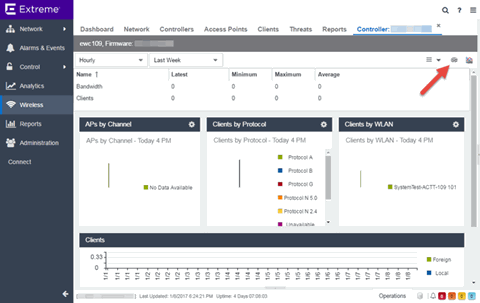
- Select the WebView icon (
 ) at the top right of the Wireless Controller Summary page.
The WebView opens for the controller. - Select the VNS tab.
The VNS tab opens.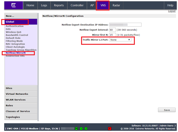
- Select Netflow/MirrorN from the left-panel.
The Netflow/MirrorN Configuration page opens. - Select None from the Traffic Mirror L2 Port drop-down list.
- Select the Save button.
NOTE: The Mirror Port in the Wireless Control Flow Sources section of the Analytics > Configuration > Configuration tab is not available when the Traffic Mirror L2 Port is disabled. - Select WLAN Services from the left-panel.
The WLAN Services page opens.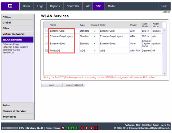
- Select a wireless LAN in the table.
The WLAN page opens for the selected wireless LAN.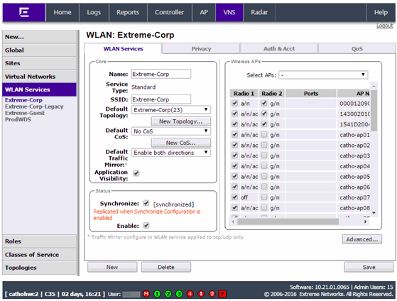
- Select the Advanced button.
The Advanced window opens. - Scroll to the bottom of the window and ensure the Netflow drop-down list is set to Enable.
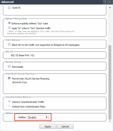
- Select the Apply button.
The wireless controller is now configured.
| NOTE: | Rx Packets and Rx Bytes can incorrectly be 0 when flow data is gathered via a wireless controller running version 10.21 or higher. Additionally, application response times and some meta data can be blank. This is a known issue and will be addressed in a future release. |
Configure ExtremeXOS/Switch Engine Identity Manager to Send Events to ExtremeCloud IQ Site Engine
This chapter describes how to use the Identity Management — Configuration script on a Summit series or Black Diamond series switch to send events to ExtremeCloud IQ Site Engine.
In order to run the Identity Management — Configuration script on a device, you must be a member of an authorization group assigned the ExtremeCloud IQ Site Engine Suite > Common Web Services > Web Services APIs Read/Write Access capability.
To run the Identity Management — Configuration script on a device:
- Open the Network > Devices tab in ExtremeCloud IQ Site Engine.
- Right-click a Summit series or Black Diamond series switch in the Devices table or in the Device Groups left-hand panel.
- Select the Identity Management — Configuration script in the Scripts > ExtremeControl menu. The Run Script window opens.
- On the Device Selection tab, the selected device is automatically included. Use the arrows to add additional devices or remove devices and to control the order of the selected devices.
- Select Next.
- On the Overview tab of the Device Settings tab, set the configuration properties for the script. If desired, select the Description tab to view the description defined for the script.
- Stop on error? — Indicates whether the script stops if an error occurs.
- Target Server IP Address — The IP address to which notifications are sent.
- Entering a value of $serverIP automatically enters the IP address of the ExtremeCloud IQ Site Engine server IP.
- Enter the IP address of the ExtremeControlengine if using the Extreme NetworksExtremeControl solution.
- Target Server Type — Selecting ExtremeCloud IQ Site Engine monitors the IP, username, and port of the user accessing the device. Users with the Extreme Networks ExtremeControl solution can select nac, which provides you with the ability to run Kerberos authentication (if enabled) on the device.
- Target Server Username — The username of the user to which the web service request is made.
- Target Server Password — The password of the user to which the web service request is made.
- Target Server HTTPs Port — The port that the ExtremeCloud IQ Site Engine server or Access Controlengine uses for HTTPS communication. The default port is 8443, but if the port was changed when configuring the ExtremeCloud IQ Site Engine server or Access Controlengine, enter the custom port used.
- XML Target Name — The name of the targets on the switch to which IDM events are sent. Using the default predefined XML Target Name creates a unique name for each server.
- Choose Action — The action that occurs on the device when the script is run.
- Enable ID Monitoring — This option sets up the XML notification, configures ports for Identity Management (if specified), and enables or disables ports for devices you can use with Identity Management.
- Manage Ports — This option only configures ports for Identity Management (if specified).
NOTE: In order to give elevated access to users when using the Kerberos authentication type on the device, the Target Server Type must be nac to allow the Access Controlengine to learn the Kerberos traffic. - On the Run-Time Settings tab, set the run-time settings for the script (for more information about defining run-time variables when creating a script, see Specifying Run-Time Settings for a Script).
- Save configuration in the background after running script successfully — Device configuration is saved after the script is run.
- Timeout if script is not completed on each device (in seconds) — The amount of time in seconds before a timeout occurs if a device does not respond.
- Run now, don’t save as a task — Select to run the script now and do not save the script as a task.
- Save as a task and run now — Select to run the script now and save it as a task. Type a name for the task in the Task Name box below. The task appears on the Script Tasks tab (see "Save Script as a Task").
- Save as task. I’ll run later — Select to save running the script as a task. The script does not run at this time. Type a name for the task in the Task Name box below. The task appears on the Script Tasks tab (see "Save Script as a Task").
- Select Next. On the Verify Run Script tab, verify your script selections, and then select Next.
- Select Next.
- On the Results tab, you see the results of the script including any errors.
- Select Close.
Schedule Tasks
The Scheduled Task tab allows you to configure ExtremeCloud IQ Site Engine to automatically perform the following tasks:
- Generate a subset of available reports in PDF format
- Run a script or workflow
- Set SMTP Email Server Options to use when the scheduled task sends an email notification.
- Discover newly added devices
Create a New Scheduled Task
- Launch ExtremeCloud IQ Site Engine.
- Select the Tasks tab and select the Scheduled Tasks tab.
- Select the Add button. The Add Scheduled Task window opens.
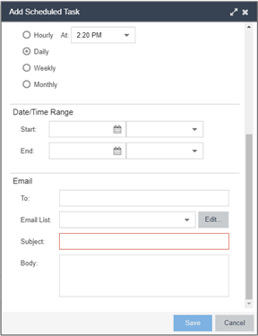
If no SMTP email settings are configured, the SMTP Email Server window also opens, where you can define the SMTP email settings. You can also configure the SMTP email settings in the SMTP Email Options tab.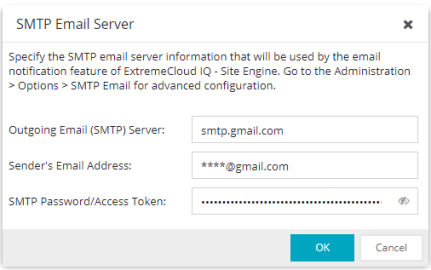
- Enter the outgoing SMTP email settings, if necessary, and select OK.
- Select the type of task from the Type drop-down list in the Add Scheduled Task window:
- Device Export — Exports the list of devices on your network from the Network > Devices tab.
- Disable Alarms — Disables enabled alarms for the amount of time you define on a scheduled basis. Use this task to avoid alarms during times you reserve for network maintenance activity. You can manually ignore enabled alarms on the Alarm Configuration tab.
- FlexReports — Creates a FlexReport for the devices you select on a scheduled basis.
- FlexViews — Creates a FlexView for the devices you select on a scheduled basis.
- Compliance — Emails the most recently run ExtremeCompliance report on a scheduled basis in PDF format.
- Port Usage — Creates a Port Usage report for the devices you select on a scheduled basis.
- Port Usage Details — Creates a Port Usage Details report for the devices you select on a scheduled basis.
- Reporting — Emails a report you select (created on the Report Designer tab) on a scheduled basis.
- Scripting Task — Runs a script saved on the Saved Tasks tab on a scheduled basis.
- Support — Emails debugging data on a scheduled basis that provides information to Extreme Networks Support in the event of an issue with your network. Only select this option if instructed to do so byExtreme NetworksSupport.
- Site — Runs a device discover for a site (created on the Site tab) on a scheduled basis.
- Workflow Task — Runs a workflow saved on the Saved Tasks tab on a scheduled basis.
- Select the report, saved task, support task, or site you want to schedule in the Report Name, Saved Task Name, Support Task Name, or Site to Discover drop-down list, respectively. Depending on what you select, you may need to make other selections such as specifying the source engine or controller.
- Edit the task name and description, if desired.
- Select or deselect the Enabled checkbox to enable or disable the task, respectively. A disabled task is not performed.
- Select whether you want the task to occur on an hourly, daily, weekly, or monthly basis.
- Hourly — specify the minute each hour you want the task performed.
- Daily — specify the time each day you want the task performed.
- Weekly — specify the day or days of the week and the time you want the task performed.
- Monthly — specify the day of the month and the time you want the task performed.
- Specify a start and end date and time for the task, if desired.
- Enter an email address or list of email addresses (separated by semicolons) to which generated PDF reports are sent in the To field, if desired.
- Select a list of email addresses to which PDF reports are sent in the Email List field, if desired.
Select the Edit button to create a new email list or edit an existing email list. - Enter the subject line and body text for the email, if desired.
- Select Save.
The task appears in the Scheduled Tasks table.
Additionally, use the toolbar buttons to edit, copy, or delete the task. The Refresh button updates the Scheduled Tasks table to display any recent changes. Selecting the Disable button causes a task not to run without deleting it from the Scheduled Tasks table.
Select the Run button to run the scheduled task immediately, if desired.
Select the SMTP button to open the SMTP Email Server window to edit your outgoing email options.
For more information about SMTP and an example for how to configure GMAIL OAUTH, see Examples and How-tos for using OAUTH with Gmail.
For more information about SMTP and a procedure for how to configure Office 365, see How-to Enable SMTP with Microsoft Office 365.
Create a Variable
Use the Custom Variables tab on theSites tab to configure variables. Variables you create serve as a placeholder for a specific value. Use variables you create in a configuration template, script or workflow, in a CLI command, or in a third-party application via the Northbound Interface.
To create a variable:
- Access the Network > Devices tab.
- Use the left-panel drop-down list and select Sites.
- Select the site in which you are adding the variable.
- Select the tab displaying the site name in the right-panel.
- Select the Custom Variables tab.
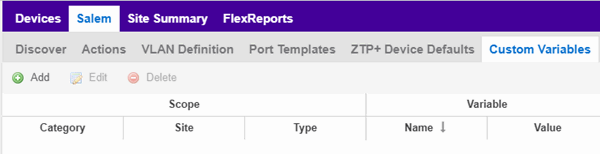
- Select Add to add a new row to the table.
- Select a Category, Site, and Type in the Scope section of the table.
- Enter a Name, select a Type, and enter a Value in the Variable section of the table.
- Select Update to save the new variable to the table.
- Select Save to save the new variable to the site.
Creating Scripts
This chapter describes the scripting functionality built into ExtremeCloud IQ Site Engine and describes how to use ExtremeCloud IQ Site Engine to create scripts.
ExtremeCloud IQ Site Engine Scripts Overview
ExtremeCloud IQ Site Engine scripts are files containing CLI commands, control structures, and data manipulation functions. ExtremeCloud IQ Site Engine scripts can be executed on one or more devices or ports: simultaneously on multiple devices or ports, or on one device or port at a time.
ExtremeCloud IQ Site Engine allows you to create ExtremeCloud IQ Site Engine tasks, which run a script on specified devices or ports at specified times, either on a one-time or recurring basis. Tasks execute the script according to a schedule you configure.
In general, ExtremeCloud IQ Site Engine scripts support syntax and constructs from the following sources:
- Python scripting language — Create scripts using the Python syntax. The script can access ExtremeCloud IQ Site Engine data through API and NBI calls, and can use variables from the Custom Variables tab. Python scripts can be saved as tasks, and then run from the Tasks menu or run as scheduled tasks.
To execute a Python script on a device using an ExtremeXOS/Switch Engine operating system, useType= JSON-RPC-Python. For other device operating systems, useType=Python.
- TCL scripting language version 8.1 — Create scripts using TCL syntax. The script can send CLI commands to devices in ExtremeCloud IQ Site Engine and the resulting responses can be use by the script in ExtremeCloud IQ Site Engine. TCL scripts can be saved as tasks, and then run from the Tasks menu or run as scheduled tasks.
To execute TCL scripts on a device using an ExtremeXOS/Switch Engine operating system, abbreviated commands (such assh vlaninstead ofshow vlan) can be used in the script if the commands use the prefixCLI.
Example:CLI sh vlan
To copy the whole script to an ExtremeXOS/Switch Engine device, useType=JSON-RPC-CLI, the script will be executed in theenable cli scriptingsession. For other device operating systems, useType=TCL.
For general information about the TCL scripting language, see www.tcl.tk. For more information about using CLI scripting, see the ExtremeXOS/Switch Engine User Guide.
- ExtremeXOS/Switch Engine CLI commands — ExtremeXOS/Switch Engine CLI commands can be combined into a script to execute in sequence using
Type=CLI. The CLI script is saved and executed in the Scripts tab. However, if the sequence of command needs to be accessed or scheduled as a task, thenType=TCLshould be used as the script type instead. An ExtremeCloud IQ Site Engine script is sent to the device or port and the response can be used by the script.
CLI commands can also be executed for selected devices using the CLI Commands feature on the Tasks menu for devices. The commands are executed sequentially and can be saved to a script but not saved to a task.
Abbreviated ExtremeXOS/Switch Engine commands do not work unless you prefix the shortened command with CLI. For example, to abbreviateshow vlan, typeCLI sh vlan.
Bundled ExtremeCloud IQ Site Engine Scripts
ExtremeCloud IQ Site Engine includes a number of sample scripts you can use as templates for your own ExtremeCloud IQ Site Engine scripts. These scripts perform such tasks as enable/disable ports, apply ACLs, restart engines, and configure VLANs.
The sample scripts included with ExtremeCloud IQ Site Engine are available to users with an Administrator role. The XML source files for the scripts are located at <install directory>\appdata\scripting\bundled_scripts.
The ExtremeCloud IQ Site Engine Script Interface
To display the scripts configured in ExtremeCloud IQ Site Engine, select the Tasks tab, then select the Scripts tab.
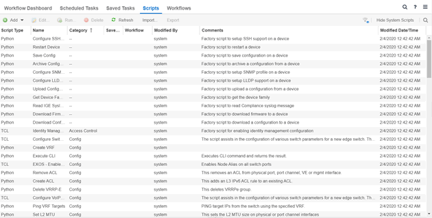
The Scripts tab contains the following information:
- Script Type — The language in which the script is written.
- Name — The name of the script. The script Name is defined when adding the script and can not be edited.
- Category — The script category, if configured.
- Saved Tasks — Indicates whether the script is configured as a saved task and is available on the Saved Tasks tab.
- Workflow — Indicates if the script is included in a workflow.
- Modified By — The name of the last user to modify the script. System scripts that are packaged with ExtremeCloud IQ Site Engine are indicated as system.
- Comments — Comments or a description of the script.
- Modified Date/Time — The date and time the script was last modified.
To view a script, double-click it. Note: Systems scripts cannot be edited. However, system scripts can be duplicated (using Save As ) and the duplicated script can be edited. The duplicated script shows the last user to edit the script in the Modified By field.
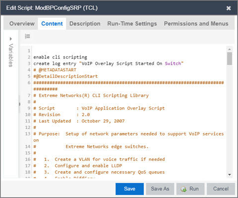
The ExtremeCloud IQ Site EngineEdit Script window allows you to add content to a script, set values for parameters, specify run time settings, and specify the ExtremeCloud IQ Site Engine users with permission to run the script.
Depending on the type of script you are editing, the following tabs may appear in the ExtremeCloud IQ Site EngineScript Editor window:
- Overview — Displays fields to enter script parameters. The contents of this tab are derived from the metadata specified in the script.
- Content — Displays the script in a text editor window, where you can modify it directly.
- Description — Contains descriptive information about the script. The script description is specified in the metadata section of the script.
- Runtime Settings — Specifies script settings applied when the script is run.
- Permissions and Menus — Specifies ExtremeCloud IQ Site Engine user roles with the ability to run the script, and whether or not, and where, the option to run the script appears in the ExtremeCloud IQ Site Engine interface, such as on a menu or in a shortcut menu.
- Network OS — Allows you to select the Network Operating Systems that support the script. The script is available on a device's Tasks submenu when the device's Network OS matches one of the Network Operating Systems defined for the script.
Managing ExtremeCloud IQ Site Engine Scripts
With scripting, you can:
- Create an ExtremeCloud IQ Site Engine Script
- Specify Runtime Settings for a Script
- Specify Permissions and Run Locations for Scripts
- Run a Script
- View Script Results
- Edit a Script
- Delete a Script
- Import Scripts into ExtremeCloud IQ Site Engine
- Export a Script
- Save Script as a Task
Create an ExtremeCloud IQ Site Engine Script
- Select Scripts on the Tasks tab.
- Select the Add button.
-
Select the type of script you are creating:
- TCL — A Tool Command Language script. Use TCL instead of CLI if you need to use the script in a task. Proceed to step 5.
- Python — A Python script. Proceed to step 5.
- JSON-RPC-Python — Machine to Machine Interface (used to send a Python script to an ExtremeXOS/Switch Engine device). Proceed to step 5.
- JSON-RPC-CLI — Machine to Machine Interface (used to send CLI commands to an ExtremeXOS/Switch Engine device). Proceed to step 5.
- CLI — A CLI command script. Use CLI instead of TCL if you do not need to use the script in a task. Proceed to step 4.
- When selecting CLI from the Add drop-down list, the Add Script window opens, where you can enter the CLI commands for the script. Select Variables to open the Select Variables window, from which you can select variables you define on the Custom Variables tab.
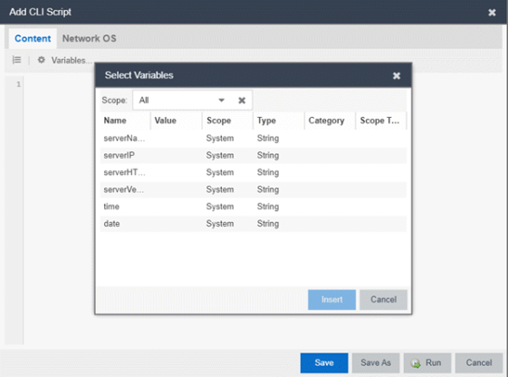
Use the Scope drop-down list to select either All, Custom, or System from the drop-down list, depending on how you configured the variable you are inserting. Select Insert to add the variable to your script.
Select Save to save the CLI script on the Scripts tab or select Save As to save the script to the ExtremeCloud IQ Site Engine server.
Select Run to run the CLI script immediately. - When selecting the TCL, Python, JSON-RPC-Python, and JSON-RPC-CLIscript types, the Add Script window also opens, but contains the following tabs:
- Overview — Use to enter script parameters. The contents of this tab are derived from the metadata specified in the script.
- Content — Use to modify the script directly in a text editor window.
- Description — Add descriptive information about the script. The script description is specified in the metadata section of the script.
- Runtime Settings — Specify script settings applied when the script is run.
- Permissions and Menus — Specify ExtremeCloud IQ Site Engine user roles with the ability to run the script, and whether or not, and where, the option to run the script appears in the ExtremeCloud IQ Site Engine interface, such as on a menu or in a shortcut menu.
- Select the Network OS tab to select the select the Network Operating Systems that support the script.
| NOTE: | Select Unknown when creating scripts or workflows that include devices before their Network OS has been determined (e.g. onboarding new devices). |
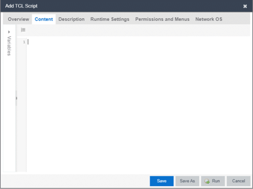
- Type the metadata tags
#@DetailDescriptionStartand#@DetailDescriptionEndbetween the tags#@MetaDataStartand#@MetaDataEnd, and then type a detailed description between these detailed description tags. This description appears on the Description tab. - Place variable definition statements in the metadata section (between
#@MetaDataStartand#@MetaDataEndtags).
Select a variable by expanding the Variables menu on the left of the Content tab. A list of system variables appears under Variables. To add a variable to the script, double-click the variable. - Enter script commands after the metadata section of the script.
The following are examples of types of script commands supported in ExtremeCloud IQ Site Engine:- ExtremeXOS/Switch Engine 12.1 and later CLI scripting commands
- TCL commands
- Constructs
- Select the Runtime Settings tab to specify runtime settings.
- Select the Permissions And Menus tab to specify which ExtremeCloud IQ Site Engine user roles have permission to run the script, and whether or not, and where, the script appears in the menu or in a shortcut menu.
- Select the Network OS tab to select the select the Network Operating Systems that support the script.
- Select Save. The Save Script window appears.
| NOTE: | Select Unknown when creating scripts or workflows that include devices before their Network OS has been determined (e.g. onboarding new devices). |
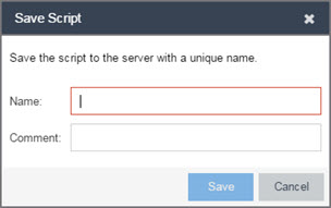
- Type a name for the script file in the Name field and a comment about the script in the Comment field, if necessary.
- Select Save.
- Select Run to run the script now or Cancel to run the script at a later time.
Specify Runtime Settings for a Script
To specify the runtime settings for a script, select the Runtime Settings tab.
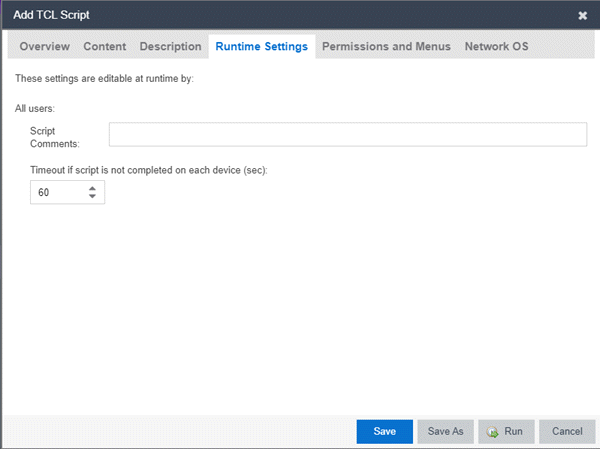
Use this tab to specify the following settings:
- Script Comments — Use this field to enter comments or a description of the script.
- Timeout if script is not completed on each device (in seconds) — Select the maximum length of time the script runs on each device or port (in seconds) before the process ends. This timeout value applies to each device or port independently.
Specify Permissions and Run Locations for Scripts
Specify which ExtremeCloud IQ Site Engine user roles have permission to run the script, and whether or not, and where, the script appears in the menu or in a shortcut menu.
Select the Permissions and Menus tab to set permissions and menu locations for the script.
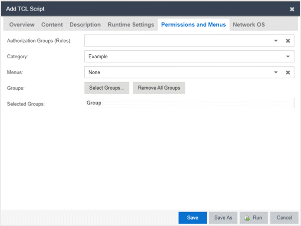
- Authorization Group (Roles)
- Select the Authorization Group credentials required to execute the script from the drop-down list.
- Category
- Select the Category group from the drop-down list, which defines the Tasks submenu in which the script is grouped throughout ExtremeCloud IQ Site Engine. The default category is Example.
- Menus
- Select the Tasks submenus in ExtremeCloud IQ Site Engine in which you want the script to display from the drop-down list. Select Multi-Device for User Device Group scripts.
Specify Network Operating System
Select the Network OS tab to select the Network Operating Systems that support the script.
| NOTE: | Select Unknown when creating scripts or workflows that include devices before their Network OS has been determined (e.g. onboarding new devices). |
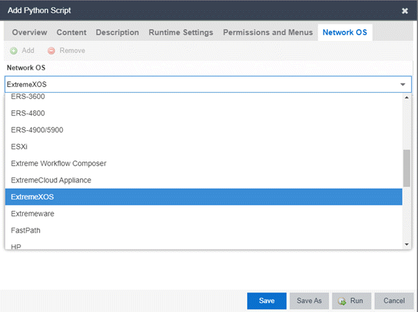
Run a Script
From the Network tab
| NOTE: | The Runtime Settings tab is unavailable for scripts run via the Network tab. To save a script as a saved task or configure a timeout when running the script, run the script via the Tasks tab. |
- Right-click the device in the Devices table or in the Device Groups left-hand panel on the Devices tab.
- Select a script in the Tasks menu. The Run Script window opens.
- On the Device Selection tab, select the device or devices against which you want to run the script. Use the arrows to add/remove devices and to control the order of the selected devices.
- Select Next.
- On the Overview tab of the Device Settings tab, set the configuration properties for the script. The options available on this tab vary depending on the script selected. If desired, select the Description tab to view the description defined for the script.
- Select Next.
The Verify Run Script tab opens. - Verify your script selections, and then select Run.
- On the Results tab, you see the results of the script including any errors.
- Select Close.
From the Tasks tab
- Select Scripts.
- On the Scripts tab, find the script in the list. If needed, filter the list by typing search terms in the Search field.
- Select the script by selecting its row and then select Run. The Run Script window opens.
| NOTE: | Only select one script. The Run button is unavailable if two or more scripts are selected. |
- On the Device Selection tab, shown below, select the device or devices against which you want to run the script. Use the arrows to add/remove devices and to control the order of the selected devices.
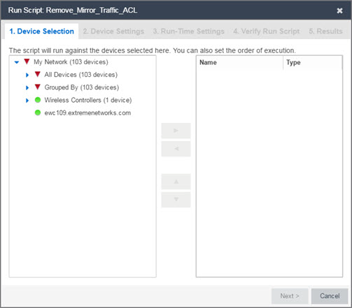
-
Select Next.
- On the Overview tab of the Device Settings tab, set the configuration properties for the script. The options available on this tab vary depending on the script selected. If desired, select the Description tab to view the description defined for the script.
- Select Next.
- On the Runtime Settings tab, configure the runtime settings for the script.
- Timeout if script is not completed on each device (in seconds) — Use to set a maximum amount of time for the script to run on each device (in seconds). This timeout value applies to each device independently.
- Run now, don’t save as task — Select to run the script immediately without saving the script as a task.
- Save as a task and run now — Select to run the script immediately and save it as a task on the Saved Tasks tab. Type a name for the task in the Task Name field.
- Save as a task. I’ll run later — Select to save the script as a task you can run later. Type a name for the task in the Task Name field. The task appears on the Saved Tasks tab.
- Select Next. On the Verify Run Script tab, verify your script selections, and then select Run.
- On the Results tab, you see the results of the script including any errors.
- Select Close.
View Script Results
When a script is run, results are stored in the <install directory>/appdata/scripting/tmp folder. The folder in which script results are stored cannot be configured.
An event is stored in the console.log file in the <install directory>/appdata/logs folder each time a script is executed. The event in the log contains the location of the audit file. These audit logs reside in the tmp directory and remain for two weeks (per user), or until the next server restart, whichever comes first. The number of audit files written to the folder is limited to 1,000 files. When the number of files exceeds 1,000, the oldest 100 are deleted.
Edit a Script
To edit a script:
- In the Tasks tab, select Scripts.
- In the scripts table, select the script you want to edit. Note: Systems scripts that are packaged with ExtremeCloud IQ Site Engine cannot be edited. However, system scripts can be duplicated (using Save As) and the duplicated script can be edited. The systems scripts are labeled system in the Modified By field, but duplicated scripts show the last user name as Modified By.
- Select the Edit button. The script opens in the Edit Script window, where you can edit the script.
- Save the script:
- Select the Save button to save your changes to the script.
- Select Save As to save a copy of this script with a new name.
The Save Script As window appears.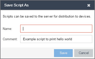
- Type a name for the script file in the Name field and a comment about the script in the Comment field, if necessary.
- Select Save.
The script is saved.
Delete a Script
To delete a script:
- In the Tasks tab, select Scripts.
- In the scripts table, select one or more scripts you want to delete.
- Select the Delete button.
- Select Yes to confirm the script deletion.
Import Scripts into ExtremeCloud IQ Site Engine
Import XML-formatted scripts into ExtremeCloud IQ Site Engine.
To import a script:
- In the Tasks tab, select Scripts.
- Select the Import button.
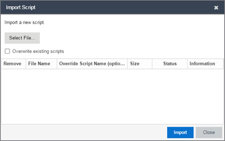
- Select Select File to navigate to the location of the script. The script appears in the grid.
- Enter a new Script Name in the Override Script Name (optional) field if you want to change the name of the script.
- Select the Overwrite existing scripts checkbox, if necessary.
- When Overwrite existing scripts is not selected and the script name displayed in the File Name field (if you did not use the Override Script Name (optional) field) or the Override Script Name (optional) field matches the name of a script in ExtremeCloud IQ Site Engine, the new script is not imported.
- When Overwrite existing scripts is selected and the script name displayed in the File Name field (if you did not use the Override Script Name (optional) field) or the Override Script Name (optional) field matches the name of a script in ExtremeCloud IQ Site Engine, the new script is imported and overwrites the existing script.
- Select Import.
- Verify the script is imported and select Close.
| NOTE: | Exported EPICenter 6.0 telnet macros cannot be imported as XML scripts. |
Export a Script
To export a script:
-
From the Tasks tab, select a script.
-
Select the Export button.
The script is exported in XML format to your browser download directory.
Save Script as a Task
When you run a script, you can save it as a task that appears in the Saved Tasks tab. This saves your device selections and runtime settings, and then allows you to manually run the script task at a later time or schedule it to run in the future either one time, or on a regular basis.
To save a script as a saved task:
- Select a script.
- Run the script and designate it as a task by selecting either Save as a task and run now or Save as task. I’ll run later on the Runtime Settings tab.
- Enter a new name for the task in the Task Name field.
ExtremeCloud IQ Site Engine saves the script to the Saved Tasks tab.
ExtremeCloud IQ Site Engine Script Reference
This section contains reference information for ExtremeCloud IQ Site Engine scripts. It contains the following topics:
- Metadata Tags
- ExtremeCloud IQ Site Engine-Specific Python Scripting Constructs
- ExtremeCloud IQ Site Engine-Specific TCL Scripting Constructs
- TCL Support in ExtremeCloud IQ Site Engine Scripts
- Entering Special Characters
- Line Continuation Character
- Case Sensitivity in ExtremeCloud IQ Site Engine Scripts
- Reserved Words in ExtremeCloud IQ Site Engine Scripts
- ExtremeXOS/Switch Engine CLI Scripting Commands Supported in ExtremeCloud IQ Site Engine Scripts
- ExtremeCloud IQ Site Engine-Specific System Variables
An ExtremeCloud IQ Site Engine script may contain a metadata section, which can serve as a usability aid in the script interface. The metadata section, if present, is the first section of an ExtremeCloud IQ Site Engine script, followed by the script logic section, which contains the CLI commands and control structures in the script. The metadata section is delimited between #@MetaDataStart and #@MetaDataEnd tags. A metadata section is optional in an ExtremeCloud IQ Site Engine script.
Use metadata tags to specify the description of the script, as well as parameters that the script user can input. The information specified by the metadata tags appears in the Overview tab for the script.
ExtremeCloud IQ Site Engine-Specific Python Scripting Constructs
Specifying the Wait Time Between Commands
After the script executes a command, the time.sleep command causes the script to wait a specified number of seconds before executing the next statement.
Syntax
time.sleep(10)
Example
# sleep for 10 seconds after executing a command
time.sleep(10)
Metadata Tags
#@MetaDataStart and #@MetaDataEnd
Indicates the beginning and end of the metadata section of the script. In order for description information and variable input fields to appear in the Overview tab for a script, the corresponding metadata tags must appear in the metadata section.
Example
#@MetaDataStart
#@SectionStart (description = "Protocol Configuration Section") Set var protocolSelection eaps
#@SectionEnd
#@SectionStart (description = "vlan tag section") Set var vlanTag 100
#@MetaDataEnd
#@ScriptDescription
Specifies a one-line description of the script. The description specified with this tag cannot contain a newline character.
Example
#@ScriptDescription "This is a VLAN configuration script."
#@DetailDescriptionStart and #@DetailDescriptionEnd
Specifies the beginning and end of the detailed description of the script. The detailed description can be multiple lines or multiple paragraphs. The detailed description is shown in the Script View tab in the script editor window.
Example
#@DetailDescriptionStart
#This script performs configuration upload from ExtremeCloud IQ Site Engine to the switch.
#The script only supports tftp.
#This script does not support third party devices.
#@DetailDescriptionEnd
#@SectionStart and #@SectionEnd
Specifies the beginning and end of a section within the metadata part of a script. You do not need to end with a #@MetaDataEnd tag, then the #@SectionEnd tag if this is the last section of the metadata. When a section starts with the #@SectionStart tag, the previous section automatically ends.
Example
#@SectionStart (description = "Protocol Configuration Section") Set var protocolSelection eaps
#@SectionEnd
#@VariableFieldLabel
Defines user-input variables for the script. For each variable defined with the #@VariableFieldLabel tag, you specify the variable’s description, scope, type, and whether it is required.
Description
Label that appears as the prompt for this parameter in the Overview tab.
Scope
Whether the parameter is global (uses the same value for all devices) or device-specific. Valid values: global, device. Default value is global.
Type
Parameter data type. This determines how the parameter input field is shown in the Overview tab. Valid value: String (the parameter input field on the Overview tab displays as a drop-down list if validValues are listed or as a text field if validValues are not listed).
readonly
Whether the parameter is read-only and cannot be modified by the user. Valid values: Yes, No. Default value is No.
validValues
Lists all possible values for a parameter. Separate each value using a comma and put into a square bracket.
Required
Indicates whether specifying the parameter is required to run the script. Valid values: Yes, No.
Example
#@VariableFieldLabel (description = "Partition:", scope = global,
#required = yes, validValue = [Primary,Secondary], readOnly=false)
set var partition ""
ExtremeCloud IQ Site Engine-Specific TCL Scripting Constructs
This section describes the TCL scripting constructs specific to ExtremeCloud IQ Site Engine:
- Specifying the Wait Time Between Commands
- Printing System Variables
- Configuring a Carriage Return Prompt Response
- Synchronizing the Device with ExtremeCloud IQ Site Engine
- Saving the Configuration on the Device Automatically
- Printing a String to the Output File
Specifying the Wait Time Between Commands
After the script executes a command, the sleep command causes the script to wait a specified number of seconds before executing the next statement.
Syntax
sleep 5
Example
# sleep for 5 seconds after executing a command
sleep 5
Printing System Variables
The printSystemVariables command prints the current values of the system variables. Specifically, values for the following variables are printed:
- deviceIP
- deviceName
- serverName
- deviceSoftwareVer
- serverIP
- serverPort
- date
- time
- abort_on_error
- CLI.OUT
Syntax
printSystemVariables
Example
# Display values for system variables
printSystemVariables
Configuring a Carriage Return Prompt Response
A special string within the script, <cr>, indicates a carriage return in response to a prompt for a command.
Syntax
<cr>
Example
# cancel download
download image 10.22.22.22 t.txt <cr>
Synchronizing the Device with ExtremeCloud IQ Site Engine
The PerformSync command manually initiates a synchronization for specified ExtremeCloud IQ Site Engine feature areas and scope.
Syntax
PerformSync [-device <ALL | deviceIp>] [-scope <EAPSDomain | VPLS> ]
If -device is not specified, the current device (indicated by the $deviceIP system variable) is assumed.
The PerformSync command is executed in an asynchronous manner so when the command is executed, ExtremeCloud IQ Site Engine moves on to the next command in the script without waiting for the PerformSync command to complete.
Examples
PerformSync -scope VPLS
Saving the Configuration on the Device Automatically
The run time settings for the script may include the option to issue the save command in the background after the script runs successfully on the device.
Printing a String to the Output File
Example
# Write Device IP address to file
ECHO "device ip is $deviceIP"
| NOTE: | The TCL puts and ECHO commands have the same function. However, the ECHO command is not case-sensitive (unless referenced inside another command), while the puts command is case-sensitive. |
TCL Support in ExtremeCloud IQ Site Engine Scripts
The following TCL commands are supported in ExtremeCloud IQ Site Engine scripts:
| after | concat | flush | info | lrange | puts | set | unset |
| append | continue | for | interp | lreplace | read | split | update |
| array | global | foreach | join | lsearch | regexp | string | uplevel |
| binary | eof | format | lappend | lsort | regsub | subst | upvar |
| break | error | gets | lindex | namespace | rename | switch | variable |
| catch | eval | history | linsert | open | return | tell | vwait |
| clock | expr | if | list | package | scan | time | while |
| close | fblocked | incr | llength | proc | seek | trace |
See www.tcl.tk/man/tcl8.2.3/TclCmd/contents.htm for syntax descriptions and usage information for these TCL commands.
Entering Special Characters
In an ExtremeCloud IQ Site Engine script, use the backslash character ( \ ) as the escape character if you need to enter special characters, for example:
- quotation marks ( “ ” )
- colon ( : )
- dollar sign ( $ ).
Example
set var value 100
set var dollar \$value
show var dollar >>> $value
| NOTE: | Do not place the backslash character at the end of a line in an ExtremeCloud IQ Site Engine script. |
Line Continuation Character
The line continuation character is not supported in ExtremeCloud IQ Site Engine scripts. Place each command statement on a single line.
Case Sensitivity in ExtremeCloud IQ Site Engine Scripts
The commands and constructs in an ExtremeCloud IQ Site Engine script are not case-sensitive. However, if a command is referenced inside another command, the inner command is case-sensitive. In this instance, the inner command case matches how it appears in the ExtremeCloud IQ Site Engine documentation.
Example (Usage of the ExtremeCloud IQ Site Engine command ECHO)
echo hi (valid)
echo [echo hi] (error)
echo [ECHO hi] (valid)
Reserved Words in ExtremeCloud IQ Site Engine Scripts
The following words are reserved by ExtremeCloud IQ Site Engine and cannot be used as variable names in a script:
- Names of system variables (see ExtremeCloud IQ Site Engine-Specific System Variables)
- Names of ExtremeCloud IQ Site Engine command extensions (see ExtremeCloud IQ Site Engine-Specific Scripting Constructs)
- Names of ExtremeXOS/Switch Engine CLI commands
- Names of TCL functions
Also, do not use a period (.) within a variable name, use an underscore ( _ ).
ExtremeXOS/Switch Engine CLI Scripting Commands Supported in ExtremeCloud IQ Site Engine Scripts
ExtremeCloud IQ Site Engine scripts support the CLI commands in this section.
$VAREXISTS
- Checks if a given variable is initialized.
- Switch Compatibility — Devices running ExtremeXOS/Switch Engine 12.1 and higher support this command.
- Example —
if ($VAREXISTS(foo)) then show var foo endif
$TCL
- Evaluates a given TCL command. The following constructs support the $TCL command:
set var if- while
- See TCL Support in ExtremeCloud IQ Site Engine Scripts for a list of supported TCL commands.
- Switch Compatibility — Devices running ExtremeXOS/Switch Engine 11.6 and higher support this command.
- Example —
set var foo $TCL(expr 3+4) if ($TCL(expr 2+2) == 4) then
$UPPERCASE
- Converts a given string to upper case.
- The following constructs support the $UPPERCASE command:
- set var
- if
- while
- Switch Compatibility — Devices running ExtremeXOS/Switch Engine 11.6 and higher support this command.
| NOTE: | The $UPPERCASE command is deprecated in ExtremeXOS/Switch Engine 12.1 CLI scripting. Use the $TCL (string toupper <string>) command instead. Example: set var foo $TCL ("foo") . |
show var
- Prints the current value of a specified variable.
- Switch Compatibility — Devices running ExtremeXOS/Switch Engine 11.6 and higher support this command.
- Example —
show var foo
delete var
- Deletes a given variable. Only local variables can be deleted; system variables cannot be deleted.
- Switch Compatibility — Devices running ExtremeXOS/Switch Engine 11.6 and higher support this command.
- Example —
set var foo bar delete var foo if ($VAREXISTS(foo)) then ECHO "thisshould NOT be printed" else ECHO "Variable deleted." endif
configure cli mode scripting abort-on-error
- Configures the script to halt when an error occurs. If there is a syntax error in the script constructs (set var / if ..then / do..while ), execution stops even if the abort_on_error flag is not configured.
- Switch Compatibility — Devices running ExtremeXOS/Switch Engine 11.6 and higher support this command.
- Example —
enable cli scripting \$UPPERCASE uppercase # should not print show varabort_on_error
ExtremeCloud IQ Site Engine-Specific System Variables
The following system variables can be set in ExtremeCloud IQ Site Engine scripts:
$abort_on_error
Whether the script terminates if a CLI error occurs: 1 aborts on error; 0 continues on error.
$CLI.OUT
The output of the last CLI command.
$CLI.SESSION_TYPE
The type of session for the connection to the device, either Telnet or SSH.
| NOTE: | Variables with TCL special characters must be enclosed in braces. For example, when using the system variables $CLI.SESSION_TYPE and $CLI.OUT in a script, they must be entered as ${CLI.SESSION_TYPE} and ${CLI.OUT}, respectively. |
$date
The current date on the ExtremeCloud IQ Site Engine server.
$deviceIP
The IP address of the selected device.
$deviceLogin
The name of the login user for the selected device.
$deviceName
The DNS name of the selected device.
$deviceSoftwareVer
The version of ExtremeXOS/Switch Engine running on the selected device.
$deviceType
The product type of the selected device.
$netsightUser
The name of the ExtremeCloud IQ Site Engine user running the script.
$isExos
Indicates whether the device is an ExtremeXOS/Switch Engine device. Possible values are True or False.
$port
Selected port numbers, represented as a string. If the script is not associated with a port, this system variable is not supported.
$serverIP
The IP address of the ExtremeCloud IQ Site Engine server.
$serverName
The host name of the ExtremeCloud IQ Site Engine server.
$serverPort
The port number used by the ExtremeCloud IQ Site Engine web server; for example, 8080.
$STATUS
The execution status of the previously executed ExtremeXOS/Switch Engine command: 0 if the command executed successfully; non-zero otherwise.
$time
The current time on the ExtremeCloud IQ Site Engine server.
$vendor
Vendor name of the device; for example, Extreme.
FlexViews
FlexViews provide a convenient way for Operations people to view device data. These views are accessible from ExtremeCloud IQ Site Engine Devices and do not require the installation of any software (including ExtremeCloud IQ Site Engine) other than the browser itself.
You can also add your own custom FlexViews in ExtremeCloud IQ Site Engine.
Configure the options on the Administration > Options > FlexView tab to determine the behavior of FlexViews in ExtremeCloud IQ Site Engine.
To launch a FlexView, you must be a member of an authorization group that is assigned the OneView > FlexView > OneView FlexView Read Access capability. To launch and edit a FlexView, you must be a member of an authorization group that is assigned the OneView > FlexView > OneView FlexView Read/Write Access capability.
This Help topic provides information on the following topics:
Browser Requirements
The following web browsers are supported:
- Microsoft Edge
- Mozilla Firefox
- Google Chrome
Enable JavaScript in your browser for the views to function. To avoid impaired functionality, enable cookies for your browser. This includes (but is not limited to) the ability to persist table configurations such as filters, sorting, and column selections.
Launching FlexViews
Use the following steps to launch and open a FlexView from the Network tab.
- Launch ExtremeCloud IQ Site Engine and select Network > Devices.
- Select one or more devices in the Devices tab left panel or from within the Devices list.
NOTE: When you select multiple devices, a FlexView may take additional time to populate with data, depending on the number of rows displayed in the particular view. Because of this, we recommend that, for interface-based FlexViews, you select five devices or fewer. - Select the Menu icon () and select View >
FlexView from the menu.
- Select a FlexView in one of the following ways:
- Expand the Bookmarks folder in the left panel to view the FlexViews that are bookmarked.
- Expand the Categories folder in the left panel. Select a Category from the left panel, depending on the type of FlexView you want to open.
NOTE: ExtremeCloud IQ Site Engine saves user-created Custom FlexViews in the My FlexViews Category. - Locate a FlexView in the right panel.
Select the Open drop-down list and select whether you want to open the FlexView in a new tab or window.
The Select FlexView window opens.
| NOTE: | The location and availability of FlexViews in the Select FlexView window changes depending on the configuration of the options on the Administration > Options > FlexView tab. |
|---|
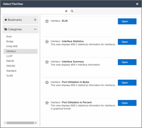
| NOTE: | Select the Star icon next to a FlexView in the right panel and select the device types for which it is applicable to save it in the Bookmarks folder in the left panel of the Select FlexViews window. This allows you to quickly find frequently used FlexViews. |
|---|
The FlexView opens in a new tab or window, depending on what you select.
Using FlexViews
FlexViews let you manipulate the table data in several ways to customize the view for your own needs:
- Select the column headings to sort column data in ascending or descending order.
- Hide or display different columns by selecting a column heading drop-down arrow and selecting the column options from the menu.
- Rearrange columns by dragging a column heading to the desired position.
- Use the Search field to filter on and search for specific FlexView data.
- Set a Refresh Interval, which automatically refreshes the data at the specified interval.
- Edit the values in FlexView table columns containing a writable MIB object.
- In the toolbar at the top of the window, select Retrieve from Devices (
 ) to clear all data and retrieve data again from selected Devices.
 - In the status bar at the bottom of the window, select Refresh from Cache (
 ) to show any new data collected since the last FlexView Update.
| NOTE: | Row creation and data exports are not currently supported in
FlexViews. |
|---|
Editing Writable Values
You can change the value in FlexView table columns that contain a writable MIB object.
- Select one or more rows in the FlexView that contain columns with writable MIB objects, right-click and select Edit Selected Rows.
- Select the writable objects you are changing and enter the appropriate values as needed.
- Select OK to enter your changes into the selected rows. The new values are written directly to the device.
The Edit Selected Rows window opens.
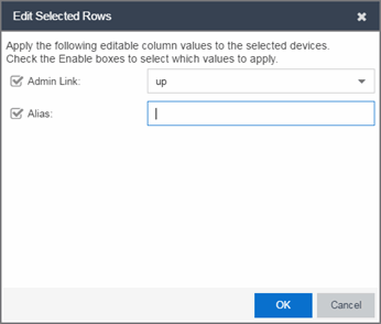
| NOTE: | Adding an alias to a port configures both ExtremeCloud IQ Site Engine and the CLI of the switch to display the character string. |
Bookmarking FlexViews
You can save frequently used FlexViews for each device type in the Bookmarks folder of the Select FlexView window. Bookmarks are shared among all ExtremeCloud IQ Site Engine users and provide your organization with the ability to select a FlexView without searching.
To add a FlexView to the Bookmarks folder, select the Category from the left panel and select the Star icon next to the appropriate FlexView in the right panel. Select the device types for which the FlexView is applicable and select Save. The FlexView is accessible from the Bookmarks folder when you access the Select FlexView window for a device that matches the device type configured for the FlexView.
Exporting Table Data
There are two methods of exporting the data in the table:
- Export to CSV
- Select to export all of the data in the table to a .CSV file. The exported data displays with any sorting, filtering, and searching applied.
- Export Selected to CSV
- Select to export the data in the currently selected row in the table to a .CSV file.
Add Custom FlexViews and MIBs
Use the instructions in this topic to add custom FlexViews and MIBs in ExtremeCloud IQ Site Engine.
To add a new FlexView to ExtremeCloud IQ Site Engine:
- Create the following directory on the ExtremeCloud IQ Site Engine server:
/usr/local/Extreme_Networks/NetSight/appdata/VendorProfiles/Stage/MyVendorProfile/FlexViews/My FlexViewsif it does not already exist. - Add your custom FlexView files (.TPL) to the
/usr/local/Extreme_Networks/NetSight/appdata/VendorProfiles/Stage/MyVendorProfile/FlexViews/My FlexViewsdirectory on the ExtremeCloud IQ Site Engine server. - Add the MIB files that correspond to your custom FlexView files to the
/usr/local/Extreme_Networks/NetSight/appdata/VendorProfiles/Stage/MyVendorProfile/MIBsdirectory on the ExtremeCloud IQ Site Engine server. - Log into the system shell (via the local console or SSH) on the ExtremeCloud IQ Site Engine server as root.
- Restart the ExtremeCloud IQ Site Engine server:
- Enter
service nsserver stop. - Enter
service nsserver start.
- Enter
VLAN Concepts
Information on:
- Egress Rules (Transmitting Frames)
- Enforcing
- Frame Types
- IGMP
- Ingress Filtering
- Priority Classification
- Verifying
- VLAN Identification
- VLAN Model
- VLAN Learning
Egress Rules (Transmitting Frames)
A device determines which frames can be transmitted out a port based on the Egress List of the VLAN associated with it. Each VLAN has an Egress List that specifies the ports out of which frames can be forwarded, and specifies whether the frames will be transmitted as tagged or untagged frames. You can add or remove ports to or from a VLAN's Egress List, thereby controlling which VLAN's frames can be forwarded out which ports.
When a frame is transmitted out a port, the device first checks the Egress List. If the port is listed on the Egress List of the VLAN associated with it, the frame is then transmitted according to the priority assigned to the frame. The frame is transmitted as tagged or untagged according to the specification in the Egress List. If the port is not on the Egress List, or if the port is not operational, the frame is discarded.
Dynamic Egress
In ExtremeCloud IQ Site Engine, you can control whether or not Dynamic Egress is enabled for a VLAN in the VLAN Definitions table. When Dynamic Egress is enabled for a VLAN, any time a device tags a packet with that VLAN ID, the ingress port is automatically added to the VLAN's egress list, enabling the reply packet to be forwarded back to the source. This means that you do not need to add the ingress port to the VLAN's egress list manually. (See Example 1, below.)
Dynamic Egress affects only the egress lists for the source and destination ingress ports. You can enable GVRP (GARP VLAN Registration Protocol), which automatically adds the interswitch ingress ports to the egress lists of VLANs. (See Example 2, below.)
When you disable Dynamic Egress for a VLAN, the VLAN effectively becomes a discard VLAN. Since the destination port is not added to the egress list of the VLAN, the device discards the traffic. If you want a VLAN to act as a discard VLAN, disable Dynamic Egress for that VLAN. (See Example 3, below.)
If an endstation is talking to a "silent" endstation which does send responses, like a printer, you will need to add the silent endstation's ingress port to the VLAN's egress list manually with a tool like ExtremeCloud IQ Site Engine Device Manager, or local management. Dynamic Egress and GVRP take care of adding the other ingress ports to the VLAN's egress list. (See Example 4, below.)
| CAUTION: | If no packets are tagged with the applicable VLAN on a port within five minutes, Dynamic Egress list entries will time out. The result is that an endstation will appear "silent" if the VLAN has not been used within that time period. For example, if there is a "telnet" rule and two users (A & B) are on ports whose role includes a service containing the "telnet" rule, if User B has not utilized the "telnet" rule within the five minute time frame, User A will not be able to telnet to User B. For this reason, the best application of Dynamic Egress is for containing undirected traffic on "chatty" clients which utilize, for example, IPX, NetBIOS, AppleTalk, and/or broadcast/multicast protocols such as routing protocols.
|
|---|
Example 1: Dynamic Egress Enabled
In this example, Dynamic Egress is enabled for VLAN 5. When source endstation A is tagged with VLAN 5, Dynamic Egress places A's ingress port (1) on VLAN 5's egress list. When destination endstation B's traffic is tagged with VLAN 5, Dynamic Egress places B's ingress port (2) on VLAN 5's egress list. The device can then forward traffic to both endstations.
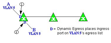
Example 2: Dynamic Egress + GVRP
In this example, Dynamic Egress is enabled for VLAN 5, and the destination endstation, B, is on a different device from the source endstation, A. When A is tagged with VLAN 5, Dynamic Egress places A's ingress port (1) on VLAN 5's egress list. GVRP then places interswitch ingress ports (2) and (3) on VLAN 5's egress list. When B's traffic is tagged with VLAN 5, Dynamic Egress places B's ingress port (4) on VLAN 5's egress list. GVRP then places interswitch ingress ports (5) and (6) on VLAN 5's egress list. The devices can then forward traffic to both endstations.
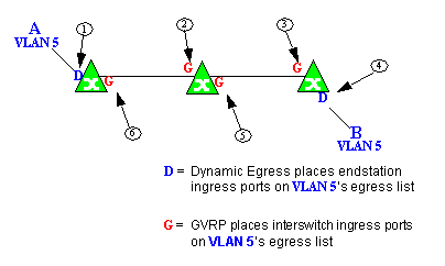
Example 3: Dynamic Egress Disabled
In this example, Dynamic Egress is disabled. When source endstation A is tagged with VLAN 5, A's ingress port is not placed on VLAN 5's egress list. GVRP places interswitch ingress ports (1) and (2) on VLAN 5's egress list. When B's traffic is tagged with VLAN 5, B's ingress port is not placed on VLAN5's egress list. GVRP places interswitch ingress ports (3) and (4) on VLAN 5's egress list. But VLAN 5 traffic for both A and B is discarded, because VLAN 5 is not aware of the ingress ports for A and B.
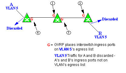
In this example, Dynamic Egress is enabled for VLAN 5, but the destination endstation, B, is a "silent" endpoint, like a printer. Endstation B does not send responses, so the Administrator must place B's ingress port on VLAN 5's egress list manually (1). When A is tagged with VLAN 5, Dynamic Egress places A's ingress port (2) on VLAN 5's egress list. GVRP then places interswitch ingress ports (3) and (4), then (5) and (6) on VLAN 5's egress list. Endstation A is then able to communicate with the printer.
GVRP
GVRP (GARP VLAN Registration Protocol) dynamically adds interswitch ingress ports to the egress lists of VLANs across a domain.
| NOTE: | If you do not want GVRP enabled on your network, you can disable it, then manually configure the interswitch ports to do what GVRP does automatically, using
MIB Tools or local management to set up your interswitch links as Q trunks. The trunk ports will be automatically added to the egress lists of all the VLANs at the time of trunk configuration.
|
|---|
GARP Timers
Set GARP timers on the device to control the timing of dynamic VLAN membership updates to connected devices. The timer values must be identical on all connected devices in order for GVRP to operate successfully.
- Join Time - Frequency of messages issued when a new port has been added to the VLAN. Possible values are 1 through 1488800 milliseconds.
- Leave Time - Frequency of messages issued when a single port no longer belongs to the VLAN. This value must be at least three times greater than the Join Time. Possible values are 1 through 1488800 milliseconds.
- Leave All Time - Frequency of messages issued when all ports no longer belong to the VLAN and the VLAN should be deleted. This value must be greater than the value for Leave Time. Possible values are 1 through 1488800 milliseconds.
Enforcing
When working with VLANs in ExtremeCloud IQ Site Engine, write the definitions in the VLAN model to selected devices or ports by selecting the Enforce button in the Configure Device window.
| NOTE: | On the X-Pedition router, enforcing will not overwrite the "System Static" VLAN (SYS_L3_Interface Name). |
|---|
Frame Types
Incoming frames are processed according to ingress rules which determine the VLAN membership and transmission priority of a frame received on a port by checking for the presence of a VLAN tag. A VLAN tag is a field within a frame that identifies the frame's VLAN membership and priority.
Frames can be tagged or untagged. A tagged frame is a frame that contains a VLAN tag. An untagged frame does not have a VLAN tag, but will be tagged when it is received on a port. A tagged frame may have already been processed by an 802.1Q switch or originated at an endpoint capable of inserting a VLAN tag into a frame. A VLAN tag may or may not contain a VLAN ID (VID), but it will always contain priority information. End systems are allowed to transmit frames with only a priority in the VLAN tag. When switches transmit a tagged frame, the VLAN tag will always include a VID along with the priority.
Tagged and untagged frames are assigned VLAN membership and transmission priority differently:
- Untagged Frame - VLAN Membership
- When an untagged frame is received on a port, if a VLAN Classification rule exists for the frame's classification type, the frame will gain membership in the associated VLAN. If not, the frame will be assigned to the VLAN identified as the port's VLAN ID (PVID).
- Untagged Frame - Priority Assignment
- When an untagged frame is received on a port, if a Priority Classification rule exists for the frame's classification type, the frame will be assigned the associated priority. If not, the frame will be assigned the port's default priority.
- Tagged Frame - VLAN Membership
- If a tagged frame includes a VID (VLAN ID), it will gain membership in the VLAN indicated by the VID. If not, and a VLAN Classification rule exists for the frame's classification type, the frame will be put into the associated VLAN. If there is no VID or classification rule, the frame will be put in the VLAN associated with the port's VLAN ID (PVID).
- Tagged Frame - Priority Assignment
- When a tagged frame is received on a port, it is assigned the priority contained in the VLAN tag.
You can set the acceptable frame type for a port in Ports.
IGMP
IGMP (Internet Group Management Protocol) is a protocol used by IP hosts and their immediate neighbor multicast agents to support the allocation of temporary group addresses and the addition and deletion of members of a VLAN. You can enable and disable IGMP in VLAN Definitions.
IGMP Intervals
You can control the following IGMP query settings in VLAN Definitions:
- Query Interval - Interval (in seconds) between general IGMP queries sent by the device to solicit VLAN membership information from other devices. By setting this interval, you can control the number of IGMP messages on a subnet. Larger values cause queries to be sent less often. The Query Interval must be greater than the Query Response interval. Valid values: 1 through 300 seconds.
- Query Response - Maximum amount of time allowed for responses to general IGMP queries. By setting this value, you can control the burstiness of IGMP messages on a subnet. Larger values result in less bursty traffic, because host responses are spread over a larger interval. This value must be less than the Query Interval. Valid values: 1 through 300.
- Interface Robustness (Robustness Variable) - Indicates the susceptibility of the subnet to lost packets. If a subnet is particularly susceptible to losses, you may wish to increase this value. IGMP is robust to (Robustness Variable-1) packet losses. The Interface Robustness value is used in the calculation of IGMP message intervals. Valid values are 2 thru 32767.
- Last Member Query Interval - Maximum amount of time (in seconds) between group-specific query messages, including those sent in response to leave-group messages. By setting this value, you can control the "leave latency" of the network. You might lower this interval to reduce the amount of time it takes the device to detect the loss of the last member of a group. Valid values: 10 through 32767 seconds.
Ingress Filtering
Ingress Filtering is a means of filtering out undesired traffic on a port. When Ingress Filtering is enabled, a port determines if a frame can be processed based on whether the port is on the Egress List of the VLAN associated with the frame. For example, if a tagged frame with membership in the Sales VLAN is received on a Port 1, and Ingress Filtering is enabled, the switch will determine if the port is on the Sales VLAN's Egress List. If it is, the frame can be processed. If it is not, the frame is dropped. You can set ingress filtering for a VLAN in Ports.
Priority Classification
Priority Classification is used to assign frames transmission priority over other frames. Priority is a value between 0 and 7 assigned to each frame as it is received on a port, with 7 being the highest priority. Frames assigned a higher priority will be transmitted before frames with a lower priority.
Each of the priorities is mapped into a specific transmit queue by the switch or router. The insertion of the priority value (0-7) allows all 802.1Q devices in the network to make intelligent forwarding decisions based on its own level of support for prioritization.
Frames can be assigned a transmission priority ;based on the default priority of the receiving switch port, regardless of the frame's classification type. However, with the addition of classification rules, frames can be assigned a priority based on the frame's classification type. Using priority classification rules, network administrators can classify a frame based on Layer 2/3/4 information to have higher or lower priority than other frames on a per port basis, allowing for better defined Class of Service configurations.
You can set the default priority for incoming frames in Ports.
Weighted Priority
Weighted priority, available on certain devices, is a way to further refine priority classification. You can control this setting in Ports.
Some devices support four transmit queues (0-3) per port. These queues can be serviced based on a strict method, meaning that all frames in Queue 3 will be transmitted before the frames in Queue 0, or based on a fair weighted method. The weighted method allows the network administrator to give a certain percentage or weight to each queue, preventing a lower priority queue from being starved.
Forwarding priority can be tuned to allocate a percentage of a port's transmit resources to the each traffic queue. This lets you adjust a strict priority scheme to guarantee that some percentage of frames from lower priority queues will always be sent. Weighted priority settings divide each port's transmit resources into 16 equal parts, which can be allocated to traffic queues in increments of 6.25% (1/16th). The total resource allocation for a port must always add up to 100%.
To understand the effect of weighted priorities, consider a device port with strict priority settings. In this case, all of the frames from the highest priority traffic queue are sent before frames are sent from any of the lower priority queues. Now, assuming four traffic queues, assign weighted priorities for the port giving 50% of the transmit resources to Queue 3, 25% to Queue 2, and 25% to Queue 1 and 0% to Queue 0. With these settings, at least 50% of the frames will be transmitted from Queue 3, at least 25% from Queue 2, at least 25% from Queue 1 and frames will only be transmitted from Queue 0 when Queue 1, 2, and 3 are empty.
Verifying
Verifying retrieves the VLAN settings on the selected devices and compares them with the settings in the selected VLAN Definitions or Ports.
Differences are indicated by a red not-equals symbol ![]() . A green exclamation point
. A green exclamation point ![]() is displayed when you select a
is displayed when you select a ![]() line in the table to the model setting that will be written to the device when you enforce. You can review the differences and make modifications to your model as needed, including updating the definitions in your model using the definitions from the selected devices.
line in the table to the model setting that will be written to the device when you enforce. You can review the differences and make modifications to your model as needed, including updating the definitions in your model using the definitions from the selected devices.
VLAN Identification
VLAN identifiers include VLAN ID's and Port VLAN ID's.
VLAN ID (VID)
802.1Q VLANs are defined by VLAN IDs (VIDs) and VLAN names.
- VID
- A unique number between 1 and 4094 that identifies a particular VLAN. VID 1 is reserved for the Default VLAN.
PVID (Port VLAN ID)
You can change a port's VLAN membership to reflect the specific needs of your network by assigning new VLAN membership to the port. When you assign VLAN membership to a port, that VLAN's ID (VID) becomes the Port VLAN ID (PVID) for the port and the port is added to the VLAN's Egress List.
- PVID
- The PVID (Port VLAN ID) represents a port's VLAN assignment. Possible values are 1 through 4094.
- Egress List
- The Egress List specifies which ports can transmit the frames associated with the VLAN.
| NOTE: | On the X-Pedition Router, you cannot assign a PVID to a port that has an interface assigned to it. |
|---|
VLAN Model
In ExtremeCloud IQ Site Engine, you can create VLAN models and enforce them across multiple network devices. A VLAN model consists of at least one VLAN Definition and one VLAN Port Template.
ExtremeCloud IQ Site Engine provides you with one VLAN model (the Primary VLAN Model) which is pre-populated with a Default VLAN (VID 1). You can further define this VLAN model, and/or you can create other VLAN models. (The Default VLAN for a model cannot be deleted.)
Once a VLAN model has been created, you can utilize it in the following ways:
- Enforce the properties of a port template on selected devices. You can also make custom edits for selected ports.
- Perform a more detailed analysis of the differences between the definitions in the VLAN model and the VLAN settings on selected devices and their ports. Using these views in the Network > Device tab, you can review the differences and make modifications to your VLAN model and/or device or port VLAN configuration as required, including updating any or all of the definitions in the model with the settings on selected devices and their ports, and writing (enforcing) a model's VLAN definitions and/or VLAN port templates to selected devices or ports.
See Create and Edit a VLAN on a Device for more information.
VLAN Learning
VLAN learning allows the creation of groups of VLANs that will share Filtered Database information (MAC address, port, and VLAN ID) according to 802.1Q Shared Learning Constraints (IEEE Std 802.1Q-1998). This helps to speed MAC to port lookups and reduce flooding, because MAC addresses will be in the same Filtering Database.
Create and Edit a VLAN on a Device
This section outlines how to create and edit a VLAN. From the Network tab, you can:
- Create a new VLAN
- Edit the ports of an existing VLAN
- Edit the name of an existing VLAN
- Remove devices from an existing VLAN
To create a new VLAN:
- Launch ExtremeCloud IQ Site Engine.
- Open the Network > Devices tab.
- Select the device from the devices list. Right-click the device and select Device > Configure Device.
The Configure Device window opens.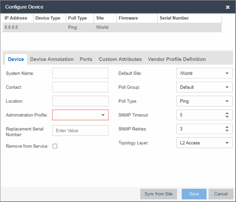
- Select the VLAN Definition tab.
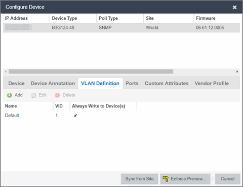
- Select the Add button.
- Enter the Name and the VID for the new VLAN.
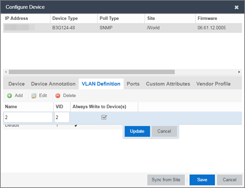
- Select Update.
The new VLAN is added to the list. - Select Enforce Preview.
- Under the Enforce Options, select the VLAN Definition checkbox and select Enforce.
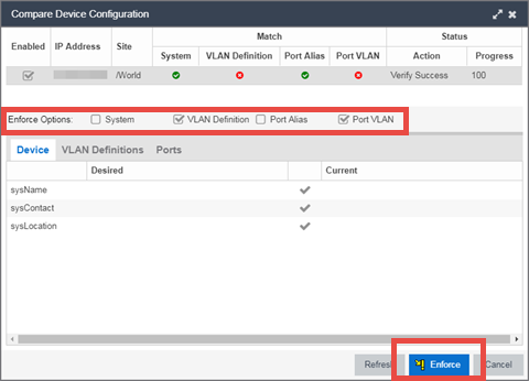
site.enforceOption.autoEnable.system=falsesite.enforceOption.autoEnable.vlanDefinition=falsesite.enforceOption.autoEnable.portAlias=falsesite.enforceOption.autoEnable.portVlan=false
| NOTE: |
By default, the checkboxes in the Enforce Options section of the window are not selected. To configure ExtremeCloud IQ Site Engine to select the checkboxes by default, open the |
The VLAN is now created and assigned to the device.
To configure the VLAN(s) on the ports
- Launch ExtremeCloud IQ Site Engine.
- Open the Network > Devices tab.
- Select the device from the devices list.
- Right-click the device and select Device > Configure Device.
The Configure Device window opens. - Select the Ports tab.
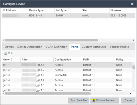
- Select the Port on which you are configuring the VLAN.
- Select Edit.
The Port is now configurable. - Change the PVID, Tagged, and Untagged options to configure the VLAN onto the port.
- Select Enforce Preview.
- Under the Enforce Options, select the Port VLAN checkbox and select Enforce.
site.enforceOption.autoEnable.system=falsesite.enforceOption.autoEnable.vlanDefinition=falsesite.enforceOption.autoEnable.portAlias=falsesite.enforceOption.autoEnable.portVlan=false
| NOTE: |
By default, the checkboxes in the Enforce Options section of the window are not selected. To configure ExtremeCloud IQ Site Engine to select the checkboxes by default, open the |
The VLAN is now configured to the Ports.
To edit the name of a VLAN:
- Launch ExtremeCloud IQ Site Engine.
- Open the Network > Devices tab.
- Select the device from the devices list.
- Right-click the device and select Device > Configure Device.
The Configure Device window opens. - Select the VLAN Definition tab.
- Select the VLAN to edit and then select the Edit button.
- Enter the new name for the VLAN.
- Select Update.
The Edit pane closes. - Select Save to exit the VLAN Definition window. The VLAN is updated.
To remove devices from a VLAN:
- Launch ExtremeCloud IQ Site Engine.
- Open the Network > Devices tab.
- Select the device from the devices list. Right-click the device and select Device > Configure Device.
The Configure Device window opens. - Select the VLAN Definition tab.
The VLAN Definition pane opens. - Select the VLAN and select Delete.